
The scenario: a mixed AGV/AMR fleet in a live warehouse
Picture a representative intralogistics site: tugger AGVs and free-roaming AMRs moving totes and pallets between receiving, racking, picking and a palletizing cell. Aisles are tight, throughput is high, and — the part that decides everything — people share the floor. Operators cross lanes, maintenance walks the racks, a forklift cuts through. The robots carry loads that overhang their own footprint. This is the environment ISO 3691-4 was written for, and it is where a clean separation between “navigation sensing” and “safety sensing” stops being academic.
The fleet has three sensing jobs that look similar and are not the same: (1) navigate — know where you are and where the aisle goes; (2) avoid obstacles — don't crash into a parked pallet or another robot, slow down when something appears ahead; (3) protect people — come to a safety-rated stop before any part of the vehicle or its load can strike a person. Jobs 1 and 2 are availability/productivity functions. Job 3 is a life-safety function with a legally required Performance Level. Confuse them and you have either a robot that nuisance-stops all day, or — far worse — one that is not actually safe.
What standard actually governs AGV/AMR safety?
ISO 3691-4:2023 — published June 2023, superseding the 2020 edition — is the master application standard for driverless industrial trucks and their systems, explicitly covering AGVs, AMRs and AGCs. Two parts of it set the spine of this case:
- Annex A Table 1 assigns required Performance Levels (per ISO 13849-1) to the safety-related parts of the control system — specifically the Personnel Detection System and the Braking System control. These are the two safety functions you must engineer to a target PL.
- The body of the standard requires personnel detection across the full width of the truck and its load in the direction of travel, an emergency stop conforming to ISO 13850:2015, and supplementary contact protection (e.g. bumpers) where optical detection cannot cover a hazard.
The consequence is blunt: the personnel-detection means must be a safety-rated detection device — not an obstacle-avoidance LiDAR. That single sentence is why the rest of this page exists. For the deeper standards walk-through, see our ISO 3691-4 driverless industrial truck guide.
What makes a laser scanner “safety-rated”? (IEC 61496-3 Type 3)
The ESPE family is IEC 61496: part 1 general, part 2 the through-beam AOPD (light curtains), and part 3 the AOPDDR — active optoelectronic protective devices responsive to diffuse reflection, which is exactly what a safety laser scanner is. A safety scanner is a Type 3 device. To earn that classification it must demonstrate a verified minimum detectable target reflectance of 1.8% and proven immunity to ambient light, dirt, background and obstruction. A Type 3 sensor is the prerequisite for realizing a SIL 2 / PL d safety function under IEC 62061 / ISO 13849-1.
A navigation/obstacle-avoidance LiDAR is not tested or certified to IEC 61496-3. It has no Type 3 type-rating, no certified diagnostic coverage, no PL/SIL classification — no matter how cleverly its software zones are drawn. That is the entire boundary. For more, read IEC 61496-3 explained: what makes a laser scanner safety-rated.

The honest two-layer sensing architecture
The design we recommend for this fleet keeps the layers physically and logically separate so a non-safety sensor can never influence the safe stop:
| Layer | Function | Device on this fleet | Safety role |
|---|---|---|---|
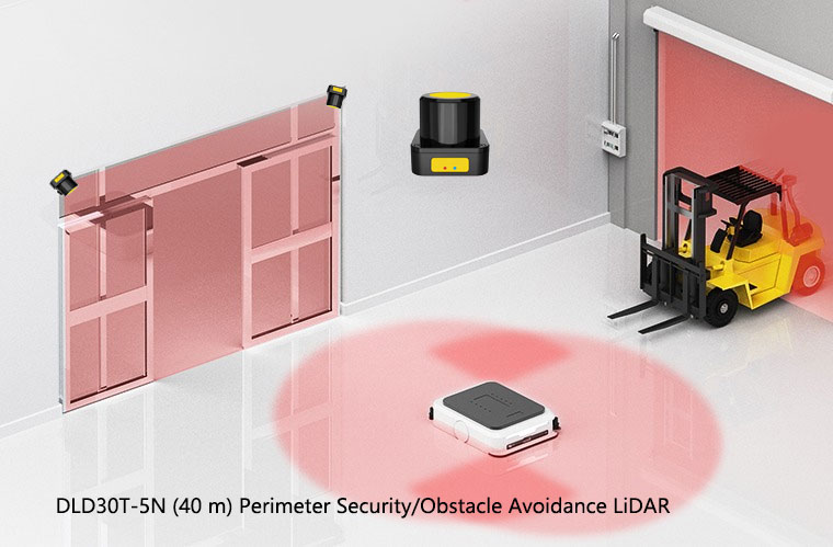
| A — Navigation & obstacle avoidance | SLAM / contour navigation, mapping, crash-avoidance warning zones that command slow-down | DAIDISIKE DLD-series 2D LiDAR (e.g. DLD30T-5N up to 40 m; DLD05A3 / DLD20A5 at 5–20 m; SDLD-05A TOF) into the vehicle controller | Non-safety (availability / productivity) |
| B — Personnel-detection protective stop | Safety-rated stop sized by ISO 13855 to the stopping distance at full load & selected speed | A certified IEC 61496-3 Type 3 safety laser scanner (selected from an appropriate safety supplier) | Safety, up to SIL 2 / PL d — mandatory per ISO 3691-4 |
| Fixed stations the fleet serves | Operator-side guarding at load/unload, palletizing, conveyor / press interfaces | DAIDISIKE DQC / DQA / DQS light curtains + DA31 safety relay | Safety (within DAIDISIKE's certified product scope) |
Layer A — the DLD's real, honest job. The DLD-series streams range data over RS485/Modbus and offers multiple PNP/NPN switching zones into the vehicle controller, which is ideal for navigation and for crash-avoidance warning fields that simply tell the drive to slow down. Be disciplined about its limits, though: DLD range is reflectivity-dependent (the DLD30T-5N reaches ≥20 m at 70% reflectance but only ≥8 m at 10%, and ≥4 m in 20k lux), so it must be derated for dark, low-reflectivity targets and bright daylight. It is a single-plane 2D sensor; it does not see a low obstacle below its plane or an overhang above it.
Layer B — the certified scanner does the protecting. The safety-rated stop is owned entirely by the certified Type 3 scanner. DAIDISIKE does not currently market a certified Type 3 unit, so for this function you select a dedicated certified safety laser scanner from an appropriate supplier — the kind of device the market knows as the SICK microScan3/nanoScan3, Pilz PSENscan, Leuze RSL400, Hokuyo UAM, Banner AG4/SX5, Keyence SZ-V or a Datasensing/ReeR safety scanner. Those names are listed nominatively to make the device class unambiguous; the choice is yours and your integrator's, against your risk assessment.
How do you size the protective field? (ISO 13855)
The certified scanner's protective field is not a guess. Under ISO 13855 the safety distance for a moving vehicle follows the EN ISO 13855:2024 form S = K × T + DDS + Z (older form S = K × T + C), where:
- S — the safety / field distance you must achieve.
- K — approach speed; the standard walking value is 1600 mm/s.
- T — total system response time: sensor + safety logic + brake. Forgetting the brake run-down here is a classic and dangerous omission.
- DDS / C — the detection-capability/depth term (tied to resolution and a minimum human body width of 150 mm).
- Z — supplement for tolerances and reflection effects.
The practical rule that ties this back to the vehicle: the distance from the protective-field front edge to the front of the vehicle must be greater than the vehicle's stopping distance at its selected speed and maximum load. A faster robot needs to “see further” because it covers more ground during its own response time, so its field grows — which is why the field sets must switch with speed and steering (slow vs fast, straight vs cornering, forward vs reverse). Keep each field only as long as the stopping distance requires; an oversized field means a bigger footprint and robots that can't pass each other. For the worked method on the fixed-guard side, our ISO 13855 safety-distance guide walks the formula step by step.
Mounting height, resolution and the 2D blind-spot trap
A safety scanner mounted near the floor (about 150 mm / 6 inches) needs a detection resolution around 60 mm to reliably detect a human leg; mounting below 300 mm calls for finer resolution so a leg cannot pass through undetected. Mount it too high and a leg slips under the beam; set the resolution too coarse and a thin limb is missed.
And never forget what a 2D scanner physically cannot do: it sees one plane only. It is blind to low-lying obstacles (a foot under a shelf, pallet stringers, the tips of forks) and to overhanging obstacles above the scan plane (a load that overhangs, a shelf edge). The load itself can cast a shadow that hides a person behind it. Design the scanner placement — and the coverage of the full truck-plus-load width — in from the start, mount low, and where coverage has gaps add the supplementary contact protection (bumpers) that ISO 3691-4 anticipates. Do not imply a 2D scanner gives full 3D coverage; it does not.

Does the whole chain need to meet the PL, or just the scanner?
The whole chain. ISO 3691-4 Annex A assigns the required Performance Level to the function, and that PL must be achieved end-to-end: scanner → safety logic / relay → brake contactors, evaluated together under ISO 13849-1 / IEC 62061. A Type 3 scanner is rated to support functions up to SIL 2 / PL d, but the realized level depends on the architecture — diagnostic coverage, the brake's response time and reliability, EDM and a deliberate manual reset on the safe-stop logic. On the fixed stations the fleet serves, that safe-stop logic is exactly the role a DAIDISIKE DA31 safety relay plays for the light-curtain guarding (PL e / SIL 3 capable, dual-channel, force-guided, EDM). On the moving vehicle, the brake and safety controller architecture must be evaluated to the PL that ISO 3691-4 demands for that function.
Common engineer mistakes on AGV/AMR fleets
These are the failures we see again and again. The first one is the whole reason this article exists:
- Treating an obstacle-avoidance LiDAR as a safety device. Using a navigation-grade LiDAR (or its software zones) as the personnel-detection means. It is not IEC 61496-3 Type 3, has no diagnostic/PL rating, and cannot satisfy ISO 3691-4 Annex A. This is the number-one mistake.
- Protective field shorter than the real stopping distance at full load and selected speed — the robot reaches the person before it stops.
- Not switching field sets with speed and steering. A small field at high speed, or a straight-ahead field while cornering, leaves the swept path unguarded.
- Wrong mounting height / resolution. Too high and a leg passes under; above 300 mm without re-checking resolution and a limb is missed.
- Ignoring 2D blind spots. Single-plane scanners are blind to low and overhanging obstacles and to shadows behind the load; plan coverage and bumpers accordingly.
- Reflective-surface and multiple-sampling misconfiguration. Shiny floors and racking cause false trips or, worse, missed detection; sampling set too low nuisance-trips on dust, set too high slows reaction and lengthens the field.
- Evaluating only the sensor, not the whole chain (sensor + logic + brake) against the required PL/SIL — and forgetting the brake response time in the ISO 13855 calculation.
- Forgetting supplementary contact protection (bumpers) where optical coverage has gaps, which ISO 3691-4 explicitly anticipates.
- Misapplying fixed-station provisions to the vehicle. Muting a light curtain without process justification, or muting geometry that lets a person stay undetected, violates IEC/TS 62046 — and muting/two-hand reasoning belongs to the fixed stations, not the moving robot.
Where light curtains and muting actually belong
The fixed stations the fleet serves — load/unload, palletizing, conveyor and press interfaces — are genuinely within DAIDISIKE's certified product scope. There the operator side is guarded by DQC / DQA / DQS safety light curtains wired through a DA31 safety relay for dual-channel monitored safe-stop logic to the contactors. IEC/TS 62046 permits muting of a presence-detection device only when the process requires it, and requires that a person cannot remain undetected in the hazardous zone when muting ends; ISO 13851 governs two-hand control devices at those stations. Keep those provisions on the fixed guarding — they do not transfer to the moving vehicle's personnel-detection scanner.
Integration checklist for the fleet
- Assign the PLs first. Use ISO 3691-4 Annex A to set the required Performance Level for the personnel-detection and braking functions before choosing hardware.
- Put the safety stop on a certified Type 3 scanner only. Never let the DLD (or any non-certified sensor) own any part of the protective stop.
- Use the DLD for navigation + warning/slow-down. Derate its range for low-reflectivity targets and daylight; respect its single-plane 2D limits.
- Size the protective field per ISO 13855 — include sensor + logic + brake response time, switch field sets with speed and steering, and cover the full truck-plus-load width.
- Mount low, resolve fine. ~150 mm height with ~60 mm resolution for leg detection; finer below 300 mm.
- Add bumpers where optics have gaps and evaluate the whole chain (sensor + logic + brake) to the required PL/SIL.
- Guard the fixed stations with DQC/DQA/DQS light curtains + DA31, and apply muting only with a real process justification per IEC/TS 62046.
The outcome
The representative fleet ends up with a clean, defensible split: the DLD-series LiDAR makes the robots navigate and avoid obstacles — mapping, contour following, and warning fields that ease them to a slow-down — while a certified IEC 61496-3 Type 3 safety laser scanner, field-sized by ISO 13855 and wired into a brake architecture verified to the ISO 3691-4 Performance Level, owns the safety-rated stop that protects people. The fixed load/unload and palletizing stations are guarded by DAIDISIKE light curtains and a DA31 relay. No non-certified sensor touches a safety function. That is the honest design — and it is the only one that passes both the audit and the real floor.