
Walk any modern warehouse or assembly plant and the floor is busier than it used to be. AGVs ferry totes between cells, AMRs weave around people on their own routes, tugger trains run fixed loops. None of them has a driver to brake when someone steps out from behind a rack. The job of stopping in time falls entirely to the vehicle’s sensing and control — and the standard that says how good that has to be is ISO 3691-4.
ISO 3691 is the series of safety standards for industrial trucks. Part 4 is the one written for the trucks with no operator on board: driverless industrial trucks and their systems. That last phrase matters. It is not only about the vehicle; it is about the vehicle plus the system it runs in — the routes, the zones, the interaction with people and fixed infrastructure. If you build, integrate or buy AGVs or AMRs for use anywhere that follows international standards, this is your reference document.
What ISO 3691-4 actually requires
Strip the standard down to its safety core and the central requirement is simple to state and demanding to meet: a driverless truck must detect a person in its path of travel and stop before contact would cause harm. Around that sit requirements on controlled motion, stopping performance, the operating zone, marking and the handling of faults. But personnel detection and safe stopping are the requirements that shape the hardware you bolt to the vehicle.
The standard is deliberately written around the safety goal rather than a single prescribed sensor. It does not tell you to fit a specific brand of scanner. It tells you the vehicle must stop in time, and it tells you to verify that it does. That is why two competent integrators can solve the same problem with different sensor layouts and both be compliant — what matters is that the chosen personnel-detection means demonstrably meets the stopping requirement.
Why the personnel-detection means is usually a safety LiDAR
The dominant way to meet the detection requirement is a safety laser scanner — a 2D LiDAR that sweeps a horizontal plane low to the floor and watches a defined region in front of the vehicle. When something breaks into that region, the scanner trips its safety outputs and the vehicle’s safety control brings it to a stop. Mounted at the right height, a single scanner covers a wide horizontal sector ahead of the truck.
The reason it is a safety laser scanner and not just a LiDAR comes down to type approval. A navigation LiDAR is built to map and localise; it is not designed or tested to fail safe. A safety laser scanner is type-tested to IEC 61496-3 — the part of the electro-sensitive protective equipment (ESPE) series that covers active opto-electronic protective devices responsive to diffuse reflection (an AOPDDR, Type 3 device). That testing is what lets you treat its detection output as a safety function. ISO 3691-4 sets the application requirement; IEC 61496-3 qualifies the sensor that meets it. You need both.
Protective fields and how field length is set
A safety laser scanner does not just emit a beam — it monitors a configured two-dimensional region called a protective field. Anything that enters the protective field triggers the stop. The art of the job is sizing that field correctly, and the governing quantity is stopping distance.
The logic runs like this. A person is detected the instant they reach the leading edge of the protective field. From that instant, time passes before the vehicle actually stops: the scanner’s response time, the reaction time of the vehicle’s safety control, and the mechanical braking time. During all of that the vehicle keeps moving. For the truck to halt before reaching the person, the protective field must extend at least the distance the vehicle travels in that total time — the braking distance plus the distance covered during the response and reaction times — with a safety margin on top. Ground clearance and the chance of under-reaching also feed into the field shape near the floor.
Notice what every term in that sum depends on: speed. The faster the vehicle, the farther it travels before stopping, and the longer the protective field has to be. This is the fact that makes a single fixed field unworkable on any vehicle that changes speed.
Speed-dependent field switching
Size one fixed protective field for full speed, and in slow zones the vehicle will stop the moment anyone comes within several metres — unusable in a tight aisle. Size it for slow speed, and at full speed the field is far too short to stop in time — unsafe. The resolution is speed-dependent field switching.
The vehicle’s safety control commands the scanner to select different protective-field sets depending on how fast the truck is travelling: a long field when running fast on an open straight, a shorter field as it slows, and a tight field at creep speed near workstations. A safety laser scanner that supports multiple switchable field cases makes this possible. Each field case is matched to a speed band, and the speeds and fields are derived from the vehicle’smeasured stopping performance — not assumed. The result is a vehicle that moves efficiently where it can and protects tightly where it must.
Many scanners also support secondary warning fields ahead of the protective field. A warning-field intrusion does not stop the truck; it slows it or sounds a signal, so an approaching person or obstacle is handled gracefully rather than with an abrupt safety stop every time. Warning fields are about availability and wear, not the safety function itself.
Blanking and reference-contour monitoring
Two further scanner features come up constantly in AGV work. Blanking (field configuration that ignores known fixed objects) lets you run a vehicle close to permanent structures without nuisance stops — but it must be applied carefully, since a blanked region is a region where a person is not detected. Reference-contour monitoring watches a known fixed boundary, such as a wall or a fixed edge, and trips if that contour changes. On a vehicle it serves as a check that the scanner is still correctly aligned and has not been knocked or tilted — an important diagnostic, because a scanner pointed slightly wrong no longer protects the field you designed.
One scanner is rarely the whole answer
A front-mounted scanner protects the direction it faces. A real vehicle moves in more than one direction and has more than one hazardous edge. Reversing, turning, load overhang, and the corners that fall outside a single scanner’s horizontal sector all create areas a single sensor cannot see. A common layout places scanners at diagonally opposite corners so that between them they cover all four sides of the truck; vehicles that reverse add rear-facing detection. The outputs are combined through an external safety controller that also handles the speed signals, the field-switching commands and the final stop command to the drive.
Mounting matters as much as sensor count. Scanner height sets where the detection plane cuts a human body; tilt changes the field geometry on the floor and can open blind spots; floor reflectivity affects detection of low-contrast objects. These are exactly the installation details that turn a correctly chosen scanner into a correctly working one — covered in our scanner mounting guide linked below.
ISO 3691-4 vs ANSI/RIA R15.08 vs ISO 10218
These three standards are easy to confuse and important to keep straight, because they cover different machines.
- ISO 3691-4 — the international standard for driverless industrial trucks and their systems: AGVs and AMRs as vehicles. This is the document that governs the mobile platform and the environment it drives in.
- ANSI/RIA R15.08 — the North American standard for industrial mobile robots. It is the regional counterpart that many AMR deployments in the United States follow, covering similar ground to ISO 3691-4 within the US standards framework.
- ISO 10218 (parts 1 and 2) — the standard for industrial robots: robot arms and robot cells. It is about manipulators and their guarding, not mobile platforms.
A plant that runs robot cells feeding a fleet of AGVs will touch ISO 10218 for the arms and ISO 3691-4 — or R15.08 in North America — for the vehicles. When a manipulator is mounted on a mobile base (a mobile manipulator), both worlds meet, and the safety case has to address the arm and the vehicle together.
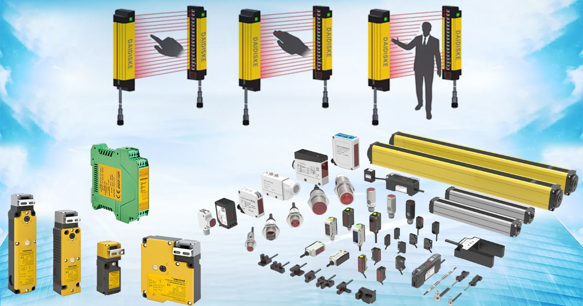
How DAIDISIKE products fit
For the personnel-detection function on a driverless truck, DAIDISIKE’s DLD-series safety laser scanners are the relevant product: a 2D LiDAR built as a safety device for protective- and warning-field monitoring on AGVs, AMRs and area guarding. Switchable field cases are what let you implement the speed-dependent field design described above.
The scanner does not work alone. Its OSSD safety outputs feed an external safety controller or a safety relay such as the DAIDISIKE DA31, which evaluates the detection signal alongside speed inputs and field-switching commands and issues the stop to the drive. Any network or fieldbus integration into the vehicle controller is handled by that external safety controller — the scanner itself is a protective device, not a fieldbus master. Designed this way, the personnel-detection chain is a verifiable safety function, which is precisely what ISO 3691-4 asks you to demonstrate.
Frequently Asked Questions
What is ISO 3691-4 and what does it cover?
ISO 3691-4 is the international safety standard for driverless industrial trucks and their systems — the part of the ISO 3691 series for industrial trucks that deals specifically with automated, operator-less vehicles such as AGVs and AMRs. It sets out the safety requirements and the means of verification for the truck and the system it operates in: personnel detection, control of motion, stopping performance, the operating zone and the interaction between vehicles, people and infrastructure. It is the international counterpart to North America's ANSI/RIA R15.08 for mobile robots.
How does ISO 3691-4 drive safety-laser-scanner protective-field design?
ISO 3691-4 requires that a driverless truck detect a person in its path and stop before contact would cause harm. In practice that is achieved with a personnel-detection means — most commonly a safety laser scanner (LiDAR) mounted low at the front. The standard's stopping requirement sets the geometry: the protective field must be long enough that, once a person is detected at its leading edge, the vehicle stops before reaching them. Field length therefore has to account for the vehicle's stopping distance at the current speed, plus the scanner's response time, the vehicle control system's reaction time, and a safety margin. The standard defines the safety goal; the protective field is how you meet it.
Why do AGVs use speed-dependent protective-field switching?
A single fixed protective field is a poor compromise: size it for full speed and the vehicle stops far too early in slow zones and tight aisles; size it for slow speed and it cannot stop in time when travelling fast. Speed-dependent field switching solves this. The vehicle controller selects a smaller field set when moving slowly and a larger one when moving fast, so the protected distance always matches the current stopping distance. A safety laser scanner that supports multiple switchable field sets, commanded by the vehicle's safety control, lets the AGV move efficiently in open runs while still stopping safely. The field cases and the speeds that trigger them are derived from the vehicle's measured stopping performance.
What role does IEC 61496-3 play for AGV safety scanners?
IEC 61496-1 is the general standard for electro-sensitive protective equipment (ESPE), and IEC 61496-3 is the part that covers active opto-electronic protective devices responsive to diffuse reflection — which is what a safety laser scanner is. A scanner type-tested to IEC 61496-3 (a Type 3 AOPDDR device) is what makes a LiDAR a safety-rated personnel-detection device rather than a navigation sensor. ISO 3691-4 expects the personnel-detection means to be a validated protective device; IEC 61496-3 is the standard that validates the scanner itself. The two work together: ISO 3691-4 sets the application-level safety requirement, IEC 61496-3 qualifies the sensor used to meet it.
How is ISO 3691-4 different from ANSI/RIA R15.08 and ISO 10218?
All three concern robot or vehicle safety but cover different ground. ISO 3691-4 is the international standard for driverless industrial trucks — AGVs and AMRs — as vehicles in an industrial environment. ANSI/RIA R15.08 is the North American standard specifically for industrial mobile robots, the regional counterpart that many AMR deployments in the US follow. ISO 10218 (parts 1 and 2) covers industrial robots and robot systems — robot arms and cells — not mobile platforms. A facility that runs both robot cells and a fleet of AGVs will touch ISO 10218 for the arms and ISO 3691-4 (or R15.08 in North America) for the vehicles.
Can one safety laser scanner protect a driverless truck on its own?
A single front-mounted scanner protects the direction of travel it faces, but a real vehicle needs coverage for every hazardous motion. A scanner mounted low at the front sees the path ahead; reversing, turning, load overhang and the corners outside a single scanner's field of view all create blind spots that one sensor cannot cover. Typical solutions use scanners at diagonally opposite corners to cover all four sides, or additional sensing for reverse travel, combined through an external safety controller. Mounting height, tilt and the floor's reflectivity also affect what the scanner can detect. Personnel detection is a vehicle-level design task, not a single-sensor purchase.
References & standards cited
- ISO 3691-4 — Industrial trucks: driverless trucks and their systems — International safety standard for AGV/AMR vehicles.
- IEC 61496-3 — Electro-sensitive protective equipment, Part 3 (AOPDDR) — Type-testing standard for safety laser scanners.
- ISO 10218-1 — Robotics: safety requirements for industrial robots — Standard for robot arms / cells (for contrast).
About DAIDISIKE: Foshan DAIDISIKE Optoelectronics Technology Co., Ltd. is a long-established industrial safety sensor manufacturer. The DLD-series safety laser scanners, Type 2 and Type 4 safety light curtains, DA31 safety relays and proximity sensors ship to OEMs and integrators across automotive, electronics, battery, packaging and material handling, with IP65 / IP67 / IP69K options for washdown environments. Designing personnel detection for an AGV or AMR fleet? Talk to our engineering team or browse the AGV/AMR safety laser scanner range.
This article is general engineering information, not a substitute for a formal risk assessment or conformity advice. For a binding assessment of a specific vehicle or installation, consult a qualified machine-safety professional and the full text of the standards cited above.