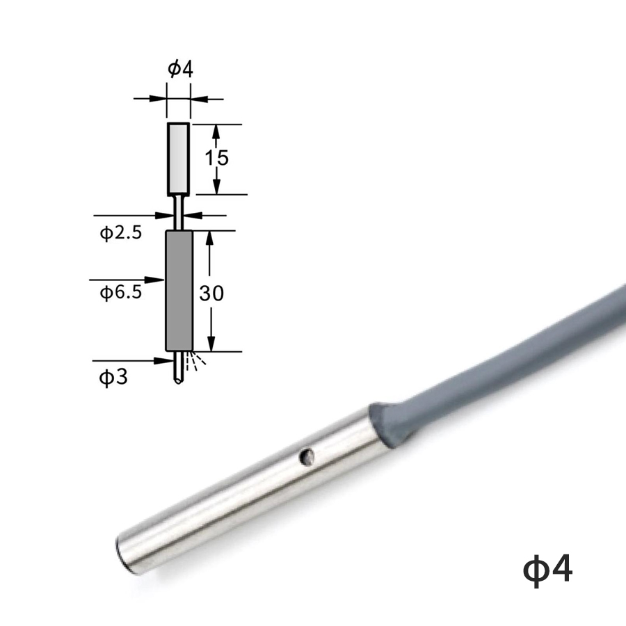
M3M4 Ultra-Small Inductive Proximity Sensor

Inductive proximity switches do one thing extremely well: detect the presence of metal at short range, reliably, for years, at low cost. No moving parts, no contact wear, fully sealed against dust and oil, standard 1 ms response time, IP67/IP68 housings rated for cutting fluid and washdown. DAIDISIKE supplies the complete cylindrical-body lineup from M3 / M4 ultra-small heads (for robot grippers and micro-assembly fixtures) through M8 / M12 / M18 / M30 workhorse bodies (for conveyors, machine tools, and indexers), in both DC three-wire (PNP/NPN) and two-wire (DC and AC) variants. Every sensor in the range carries the standard 24 VDC industrial supply, a normally-open or normally-closed output, and the IEC 60947-5-2 specifications that let it drop into any PLC input card without surprises.
Inside the sensor face is a copper coil driven by a high-frequency oscillator (typically 100 kHz to 1 MHz). The coil radiates an electromagnetic field a few millimeters out from the face. When a piece of metal enters the field, eddy currents flow in the metal — and those eddy currents extract energy from the oscillator,damping its amplitude. A simple trigger circuit detects the damping and switches the output transistor. That's the whole story.
Because the physics is entirely electromagnetic with no light, mechanical contact, or moving parts, inductive proximity switches are immune to dust, oil mist, ambient light, color, and surface finish. They're the right choice for 80% of factory-floor metal-detection jobs, and they're the reason why a typical modern manufacturing line has dozens of them quietly working in the background.
Body size correlates directly with sensing distance — a bigger coil gives a bigger field. Pick the smallest size that gives you the gap you need, plus a 30% margin for thermal drift and target tolerance.
| Body Size | Sensing Range (Sn) | Mounting | Typical Applications |
|---|---|---|---|
| M3 / M4 | 0.6 – 1.0 mm | Embedded (flush) | Robot grippers, micro-assembly, indexing pins |
| M5 / M6 | 1.0 – 1.5 mm | Embedded | Compact machine tools, electronics fixtures |
| D6.5 | 1.5 mm | Flush threaded barrel | Tight-pitch indexer position confirmation |
| M8 | 1.5 – 2.0 mm | Embedded / non-embedded | Pneumatic cylinder end-position, small conveyor |
| M12 | 2.0 – 4.0 mm | Embedded / non-embedded | General conveyor, packaging, machine tool home position |
| M18 | 5.0 – 8.0 mm | Embedded / non-embedded | Heavier conveyors, wide-pitch indexers, AGV target |
| M30 | 10 – 15 mm | Embedded / non-embedded | Robust factory I/O, presence/absence at larger gaps |
| DC 2-wire | Same as 3-wire | All M-sizes | Retrofit jobs where cable cores matter |
| AC 2-wire | Same as 3-wire | All M-sizes | Direct connection to AC contactor coils, legacy panels |
Sensing distances listed are for a standard mild-steel target. Derate by approximately 25% for stainless steel, 50% for aluminum and brass, 60% for copper.
M8 or M12 mounted in the cylinder body or on the rod-end bracket confirms full extension/retraction. Replaces unreliable reed switches with no false trips from external magnets.
M12 above the conveyor counts each metal part as it passes. On indexing tables, M8 at each station confirms target arrived before the next operation cycle.
M12 / M18 IP67 sensors replace mechanical limit switches on CNC axes and turret indexes. No contact wear, immune to cutting fluid, lifetime measured in years instead of months.
M3 / M4 ultra-small in the gripper finger confirms whether the part is gripped. No moving parts means full robot-cycle survival; small body fits the tight robot end-effector envelope.
M18 on each bolt-tightening station verifies the workpiece is present before the runtool fires. Same sensor confirms head position after the operation completes.
M18 or M30 on the AGV body, paired with a metal target on the docking station, gives mm-accuracy positioning feedback without the cost of a laser ranger for short-range applications.
M3M4 Ultra-Small Inductive Proximity Sensor
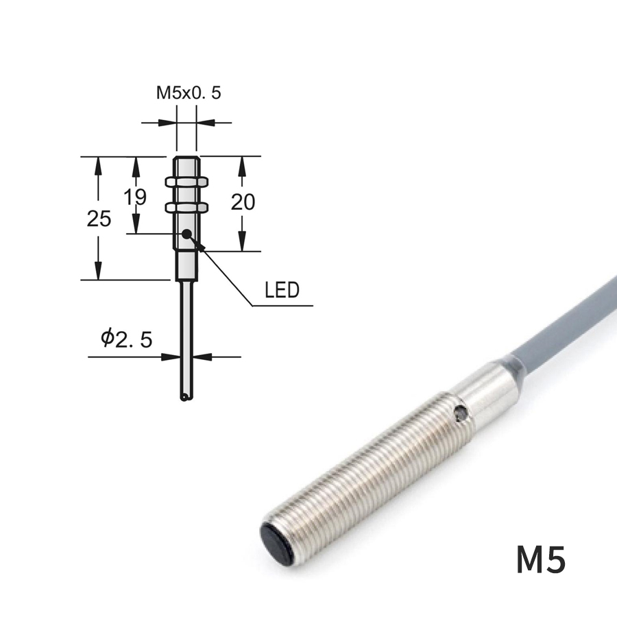
M5 / M6 Inductive Proximity Switch — High-Precision Metal Detection
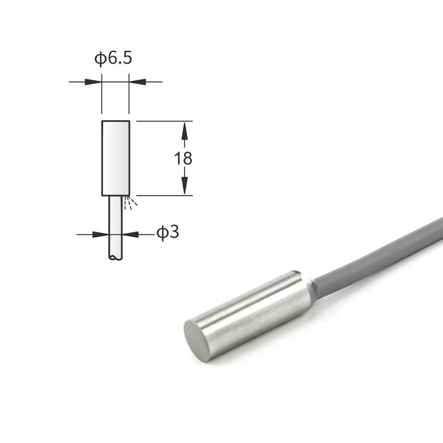
D6.5 Inductive Proximity Switch
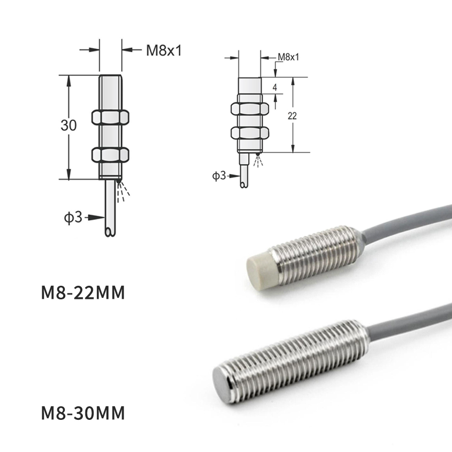
M8 Inductive Proximity Switch
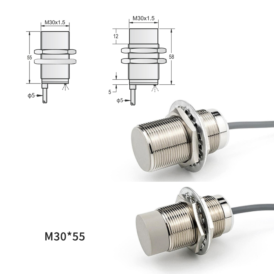
M18 / M30 Metal Sensing Proximity Switches — Three-Wire Type
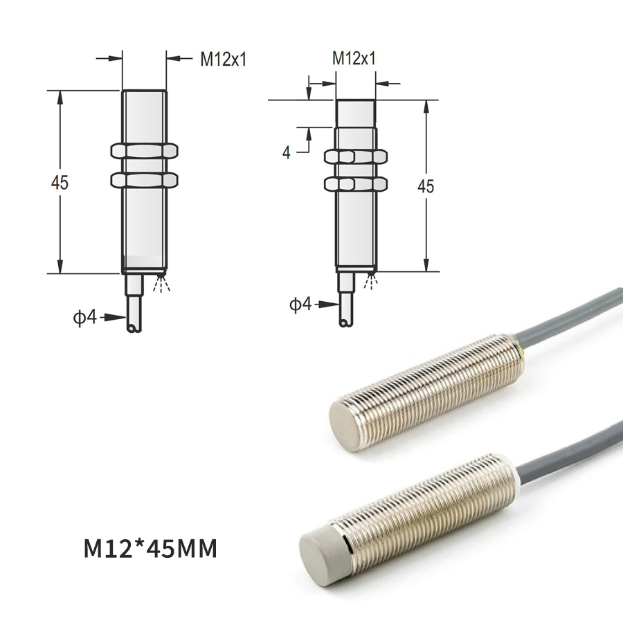
M12 Series Metal Inductive Proximity Switch
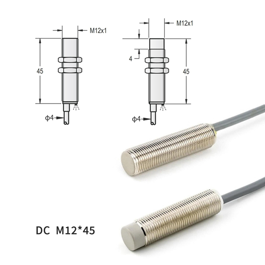
DC Two-Wire — M8 / M12 / M18 / M30 Models
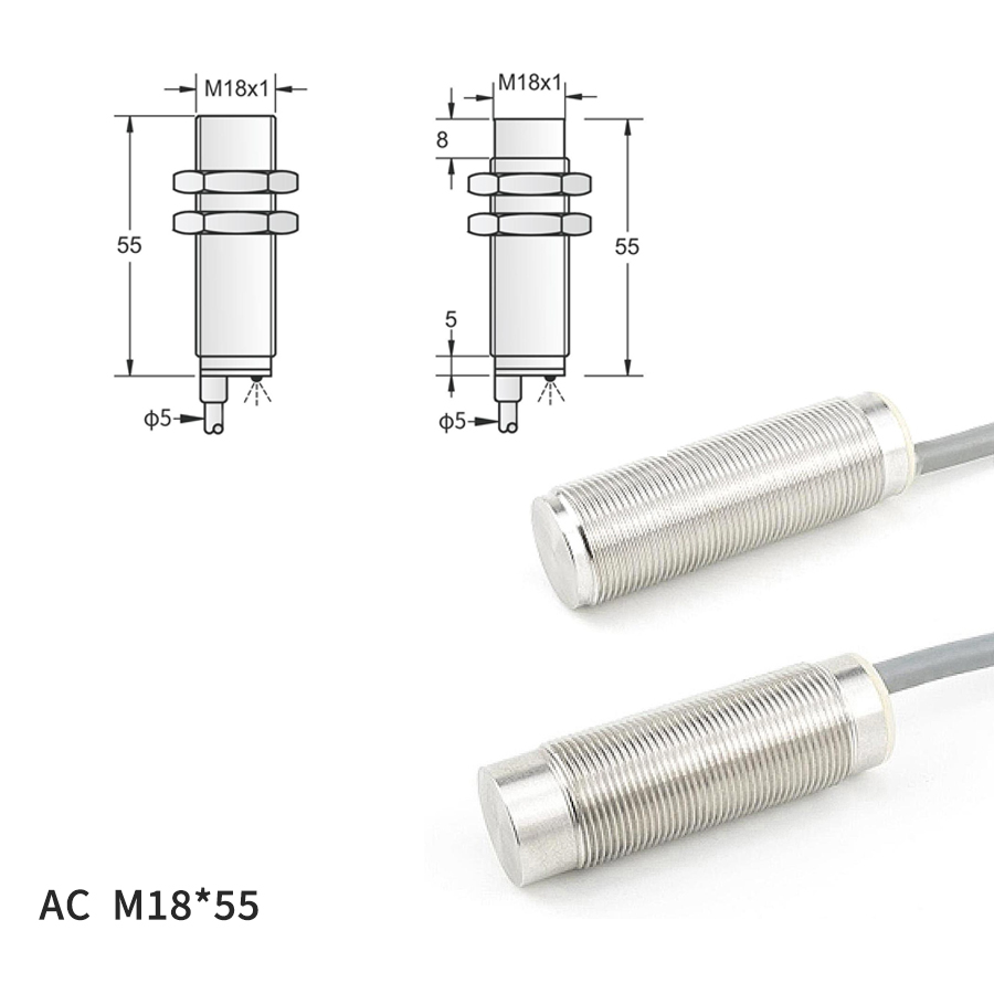
AC Two-Wire Inductive Proximity Sensors
Inside the sensor face is a coil driven by a high-frequency oscillator. The coil generates an electromagnetic field that radiates out from the active face. When a piece of metal enters the field, eddy currents are induced in the metal — these eddy currents extract energy from the oscillator, damping the oscillation amplitude. A trigger circuit detects the damping and switches the output transistor. No moving parts, no contact wear, completely sealed against dust and oil. Different metals damp the field with different efficiencies — this is why the spec sheet lists a 'standard sensing distance' for iron and a derating factor for stainless steel, aluminum, brass, and copper.
PNP (positive-switching, the European convention) is the default everywhere in the world except some Japanese and Korean factories that standardize on NPN (negative-switching). PNP sources +V from the output wire to a sinking PLC input card; NPN sinks 0 V from the output wire from a sourcing PLC input card. Both are PLC-friendly, just wire to the correct input card type. If your existing factory uses Mitsubishi or Omron PLCs imported from Japan, check the input card — it may be NPN-sinking. For new installations with Siemens, Allen-Bradley, Schneider, or Beckhoff, default to PNP unless you have a reason not to.
Normally Open (NO) means the output is OFF when no target is present and turns ON when a target enters the sensing range. This is the everyday default — counting parts on a conveyor, detecting a cylinder home position, confirming a tool change. Normally Closed (NC) does the opposite: ON when no target, OFF on detection. NC is used for fail-safe logic — if the sensor breaks or the cable falls off, the PLC sees the same OFF state as 'target detected', so the system stops rather than continuing to run blind. Many proximity switches ship with both NO and NC outputs on separate wires so you can pick at install time.
Three-wire (the most common): three separate wires for +V, OUT, and 0V. The output transistor switches independently of the supply current, so the sensor draws constant power and the output is a clean digital signal. Two-wire: the same two wires carry both supply current and the switched output (wired in series with the load, like a contact). Simpler wiring (saves one core in the cable, useful in retrofit jobs where cable count matters), but has a residual leakage current of 1-2 mA in the OFF state that some sensitive PLC inputs interpret as ON. Specify two-wire only when you know the input handles the residual current.
Inductive: metal targets only, short range (0.6-15 mm), cheapest, most robust. Use for the 80% of factory-floor metal-detection jobs. Capacitive: detects anything (metal, plastic, liquid, wood) but sensitive to ambient humidity and moisture; use for level detection in tanks or non-metallic part presence. Photoelectric: longer range (up to 50 m), works on any visible surface; use when the target is too far for inductive or when it's non-metallic. Laser: same as photoelectric but with sub-millimeter spot size; use when you need to detect a small feature (hole, edge, thin sheet) at any range. Inductive wins on cost and robustness, but only for metal.
Inductive proximity switches have no moving parts and are fully sealed against dust and oil. Lifespan in clean indoor industrial environments routinely exceeds 100 million operating cycles — typically 10+ years of three-shift operation. Failure modes, in order of frequency: (1) cable damage at the strain relief from constant flexing, often misdiagnosed as sensor failure — replace the connector first. (2) Mechanical impact on the sensor face from a crashing tool or workpiece. (3) Solvent attack on the PUR cable jacket in degreasing baths — switch to PVC or fluoropolymer jacket for chemical lines. (4) Actual electronic failure of the oscillator/trigger circuit — quite rare.
Catalog 'standard sensing distance' (Sn) is specified for a target of standard ferromagnetic mild steel, with the sensor at room temperature. Real-world derating: assured sensing distance (Sa) is typically 81% of Sn (covers manufacturing tolerance + temperature drift), and for non-standard metals you apply further correction factors (stainless steel ~ 75%, aluminum ~ 50%, brass ~ 50%, copper ~ 40%). Design for the assured Sa with safety margin — for an M12 sensor with Sn = 4 mm, design for a target gap of 2-3 mm to stay well inside Sa.