
Safety Relay vs Safety PLC — Selection Guide for Machine Safety Designers
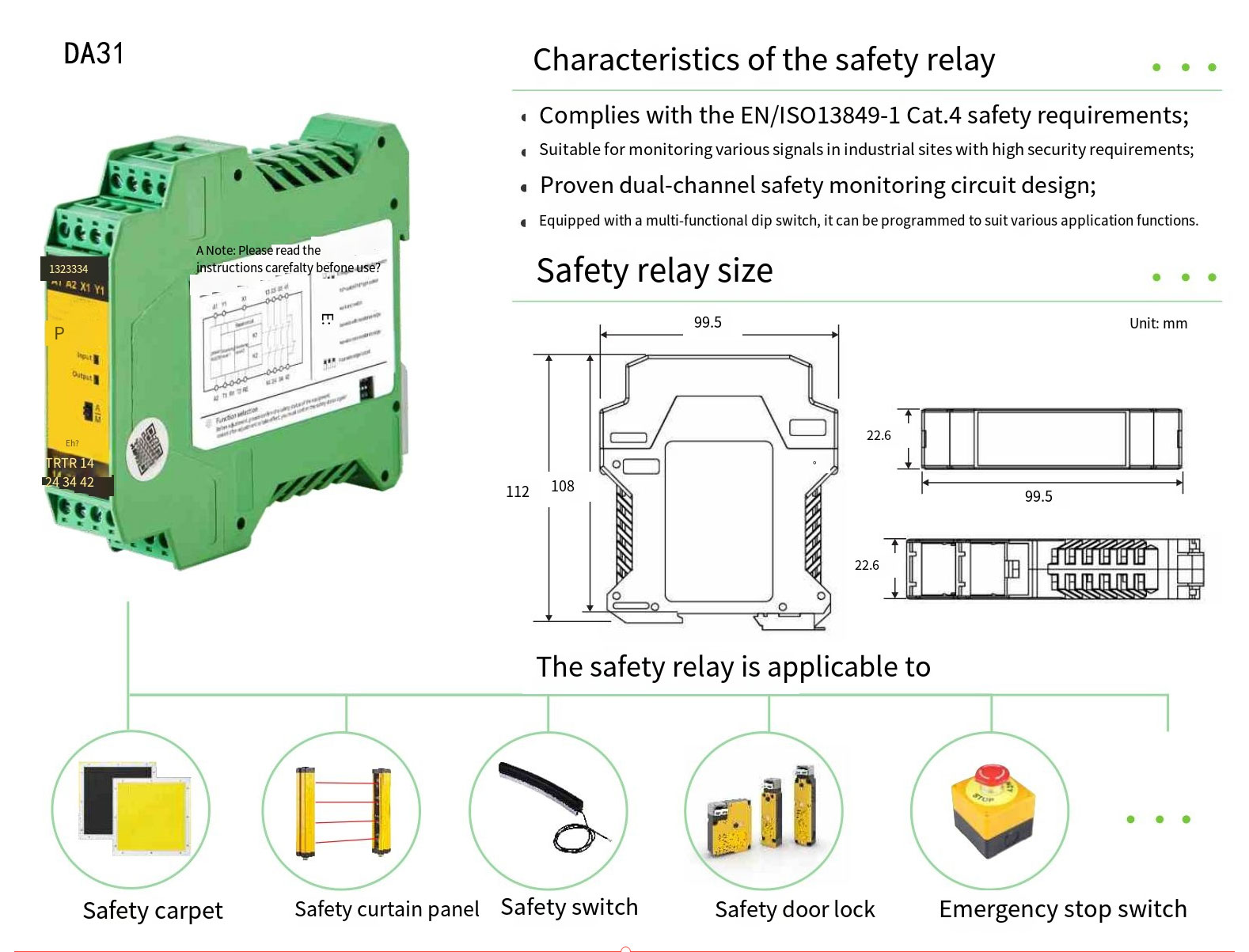
A safety relay is the right answer when the machine has one or two safety functions that do not change. A safety PLC is the right answer when there are four or more functions, when safety state crosses zones, when muting or PSDI sequencing is needed, or when the safety logic itself is part of the recipe. Both can reach PL e under ISO 13849-1 — what changes is wiring effort, commissioning time, response-time budget against ISO 13855, and total installed cost. The threshold most teams cross from relays to PLC is around three to four safety functions. The DAIDISIKE DA31 safety relay family covers the relay end of the spectrum and pairs directly with the DQE, DQC, DQO, DQT, DQR safety light curtains and the DLD safety laser scanner series.
The question of relay vs PLC for safety logic shows up on every new machine design. The answers in the field range from "always PLC, because you can change it later" to "always relays, because you don't have to certify your code." Neither extreme is right. The honest answer is architectural: the right safety logic element falls out of the safety functions you actually have, their relationship to each other and the machine's life cycle. This guide walks through both options the way an experienced control engineer would think about them, and ends with a clear decision matrix.
1. What a safety relay actually is
A safety relay is a fixed-function electromechanical or electronic device that takes safety-rated inputs — typically dual-channel OSSDs from a Type 4 ESPE, or dual-channel normally-closed contacts from an emergency stop or safety door switch — and drives safety-rated output contacts that cut power to the hazardous motion. The internals are redundant by design: two independent processing channels cross-check each other every cycle; a single internal fault drops the outputs and latches the fault.
The architectural building blocks are always the same:
- Two redundant input channels — the safety relay rejects a fault on either channel and refuses to energise outputs if the two channels disagree by more than a short tolerance window.
- Pulse-test rejection on the input side so that the OSSD test pulses from an ESPE device do not look like a fault.
- Cross-channel monitoring — two internal processing paths each compute the output state and compare; disagreement drops outputs.
- EDM (External Device Monitoring) input — a feedback path from the contactors that proves the output stage actually opened; without EDM the relay tops out at Category 3 and PL d; with EDM and the contactors wired correctly it reaches Category 4 and PL e.
- Reset logic — manual reset (operator presses a button after the safety function clears) or automatic reset (output re-energises when inputs clear); the default for personnel-protection functions is manual.
- Output stage — typically two or three normally-open safety contacts, suitable for direct contactor coil drive at 230 V AC or 24 V DC, plus one or two normally-closed auxiliary contacts for signalling to the line PLC.
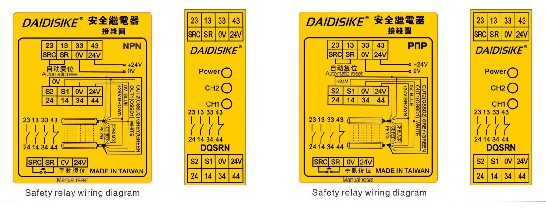
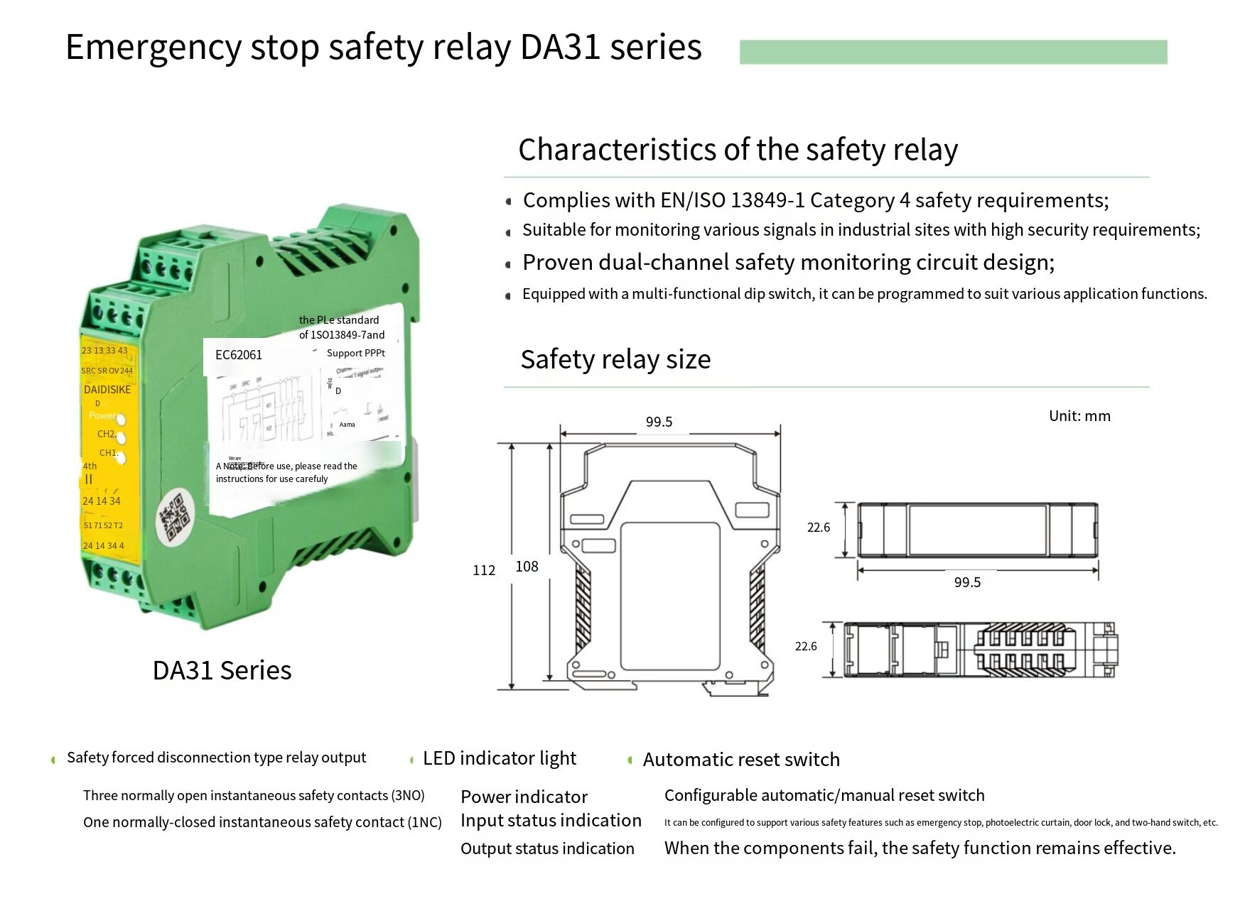
A DAIDISIKE DA31 safety relay implements exactly this pattern in a 22.5 mm DIN-rail housing. The terminal layout is conventional: S11/S12 and S21/S22 are the two safety input channels, S33/S34 is the EDM and reset loop, A1/A2 is the 24 V DC supply, 13/14/23/24 are the two NO safety output contacts, and 41/42 is a NC signalling contact for the line PLC. A second variant in the family adds delayed outputs for two-handed control and stop category 1 (controlled stop).
2. What a safety PLC actually is
A safety PLC is a programmable safety controller. Hardware-wise it has the same redundant input channels, cross-channel monitoring and safety-rated output stage as a safety relay; what changes is the logic between input and output. Instead of being hard-wired, the logic is written in a certified subset of IEC 61131-3 (typically function block diagram with a restricted instruction set) and runs on a certified runtime that has been type-approved against IEC 61508 SIL 3 and ISO 13849-1 PL e.
The architectural advantages over a safety relay are:
- Multiple independent safety functions on one device — a single small safety PLC can manage an e-stop, two light curtains, three safety doors, a two-hand control and a muting set with appropriate response-time budgets, in software, instead of with five or six cascaded relays.
- Shared safety state — variables can be passed between safety functions: "if zone 1 is in safe state, zone 2 may continue at reduced speed" is one line of code, not a panel of cross-wired relays.
- Muting and PSDI sequencing in software — defined and timed in the safety program rather than wired with auxiliary muting modules.
- Diagnostic visibility — every input, every internal state and every output is visible to the line PLC over a non-safety side channel or to an HMI for fault diagnosis, often the difference between a five-minute and a fifty-minute downtime event.
- Changeable logic — when a recipe change requires a different safety function configuration (typical on multi-product packaging lines, semiconductor cluster tools and battery formation rooms), the safety program can be updated without re-wiring the panel.
The disadvantages are also real:
- Higher unit cost — the smallest safety PLC starts at roughly four to six times the price of a DA31-class safety relay.
- Higher commissioning effort — programming a safety controller is a regulated activity; the program needs to be reviewed and validated against the safety functions in the risk assessment, and the validation evidence kept with the technical file.
- Slower response time — a safety PLC has to scan the safety program; typical scan times are 10 to 30 ms longer than a hard-wired relay, which counts in the ISO 13855 distance calculation.
- Vendor lock-in for software — a safety PLC program is not portable to a different vendor's safety controller; the relay alternative is a wiring diagram, which is.
3. The eight-question decision matrix
These are the eight questions we walk through on a new design before we commit to relays or PLC. Each is a simple yes or no. Three or more "PLC" answers usually means a safety PLC is the right call; zero or one means safety relays are cleaner.
| # | Question | If yes |
|---|---|---|
| 1 | Does the machine have four or more independent safety functions? | PLC |
| 2 | Do any two safety functions need to share state (zone interlock, conditional override)? | PLC |
| 3 | Is muting or PSDI required, with timed input sequencing? | PLC (or muting-specific relay) |
| 4 | Does the safety configuration change between recipes or product variants on the same machine? | PLC |
| 5 | Is per-zone or per-function diagnostic reporting to the line PLC or HMI required? | PLC (or relays + dedicated reporting wiring) |
| 6 | Will the machine evolve over its life — extra stations added, safeguarding revised? | PLC |
| 7 | Is the cycle time aggressive enough that 30 ms of extra response time would force a wider safety distance? | Relay |
| 8 | Does the controls engineering team lack a certified-safety-programming workflow today? | Relay |
The last two questions are the ones that pull a design back toward relays. Question 7 matters on fast presses, fast stamping cells and small robot cells where 30 ms of extra stopping time can move the safety distance by 50 to 100 mm, which can mean an extra row of beams on the light curtain or a redesigned guard. Question 8 matters because certified safety programming is a discipline of its own — the labour to set it up correctly the first time can outweigh the design value of a programmable controller on a single-machine project.
4. Cost reality — the numbers people don't quote
Direct unit-price comparison is only half the picture. A safety PLC's installed cost includes the controller, the IO modules for the channel count required, the programming software licence, the safety programming labour, the validation labour and the documentation. A safety relay's installed cost is the relay, two contactors and a few hours of wiring. For a single machine with two safety functions, the relay route can come in at roughly one quarter the installed cost of the smallest safety PLC route. Below is a representative breakdown for a single-zone robot cell with an emergency stop, a safety light curtain and one safety door switch.
| Line item | Safety relay route | Safety PLC route |
|---|---|---|
| Safety logic device | 2× DA31 safety relays (one per function, cleaner diagnostics) | 1× small safety PLC + DI/DO modules |
| Safety output contactors | 2× safety contactors with mirror contacts (EDM) | 2× safety contactors with mirror contacts (EDM) |
| Programming licence | Not required | Required, vendor-specific |
| Engineering labour | 4–6 hours (wiring drawing + panel build) | 12–20 hours (programming, validation, documentation) |
| Commissioning labour | 2 hours (loop tests, EDM check, reset test) | 4–6 hours (loop tests, program function tests, validation) |
| Documentation | Schematic, EDM loop note, reset behaviour note | Schematic, safety program listing, validation record, version log |
| Indicative installed cost | Reference baseline (1.0×) | Roughly 3.5× to 4.5× the relay baseline |
The PLC route's cost falls back toward the relay route as soon as a second or third safety function is added — those are almost free in the PLC route, whereas each one adds another relay and another panel slot in the relay route. By the time the function count reaches four, the two routes converge; by the time it reaches six, the PLC route is cheaper. The DAIDISIKE DA31 family is positioned at the cost-effective end of the relay route — appropriate for one-to-three safety function machines where a small programmable controller would be over-engineered.
5. Architectural ceiling of a single safety relay
A single DA31-class safety relay can comfortably handle:
- One dual-channel input source (one ESPE OSSD pair, or one E-stop, or one safety door switch).
- Two safety contactors as the output stage with EDM feedback.
- One reset input, manual or auto-jumpered.
- One NC signalling contact to the line PLC.
Two DA31 relays in parallel can handle two input sources ORed to the same hazard, with separate diagnostic LEDs and the ability to reset each one independently. Three or four DA31 relays cascaded can handle a moderate machine with up to four safety functions, but the wiring complexity rises fast — a common practical layout is:
- Relay 1: Emergency stop (red mushroom on the panel front).
- Relay 2: Safety light curtain at the load opening.
- Relay 3: Safety door switch on the maintenance access panel.
- The three relays' outputs are ORed at the two safety contactor coils — any one tripping drops the contactors.
Beyond four functions, or when any function needs to interact with another (a typical example is "running speed is allowed when the safety door is closed and the muting sensors are aligned"), the relay route runs out of room. That is where a small safety PLC starts to be the right answer, and the incremental cost is justified by simpler wiring and clearer diagnostics rather than by the function count alone.
6. Response-time budget and ISO 13855
The minimum-distance equation from ISO 13855 is S = K × T + C, where T is the total stopping time. T includes everything from a finger entering the safety field to the hazardous motion coming to rest, so every element in the safety chain contributes:
| Element | Typical response time | Notes |
|---|---|---|
| Type 4 safety light curtain (DQE class) | 10–25 ms | Lower for short heights, higher for long heights with more beams to scan. |
| Safety laser scanner (DLD class, Type 3) | 60–80 ms | Scanner mechanics dominate; multiple-of-revolution responses are typical. |
| Hard-wired safety relay (DA31 class) | 10–30 ms | Input filter + cross-channel check + output transition. |
| Local safety PLC | 20–50 ms | Scan cycle + IO update; depends on program length. |
| Networked safety PLC (over a safety bus) | 50–100 ms | Adds the worst-case bus message latency at the configured update rate. |
| Safety contactor opening | 15–30 ms | Arc suppression dependent; rated coil drop-out time. |
| Mechanical stopping time | 50–800 ms+ | The dominant term on most machines; measure it, do not guess. |
On a low-throughput machine the choice of safety relay or PLC adds 10 to 70 ms to a total stopping time dominated by the mechanical stop — a negligible difference in the safety distance. On a fast machine — high-speed stamping, light-load robotic pick-and-place, packaging at 60+ cycles per minute — the same 70 ms is non-negligible and can be the difference between a 200 mm and a 280 mm safety distance, which in turn decides whether the operator can reach the work area with both hands or only one. Always run the ISO 13855 calculation with the measured stopping time and the candidate safety logic element before committing to the architecture.
7. Wiring topology comparison
The wiring patterns for a single safety function look like this:
Safety relay topology
ESPE OSSD pair → DA31 input channels S11/S12 and S21/S22 → DA31 cross-channel monitoring → DA31 NO output contacts 13/14 and 23/24 → safety contactors K1 and K2 in series → motor power. K1 and K2 mirror NC auxiliary contacts in series → DA31 EDM input S33/S34. Manual reset button across S33/S34 in series with the EDM loop.
The wiring drawing is one A4 page. Commissioning is a sequence of measured tests: break each input channel one at a time and confirm the output drops; weld a contactor (simulate by inhibiting an auxiliary contact) and confirm the relay refuses to restart; verify reset behaviour.
Safety PLC topology
ESPE OSSD pair → safety PLC DI module input pair → safety program logic → safety PLC DO module output pair → safety contactors K1 and K2 in series → motor power. K1 and K2 mirror NC auxiliary contacts in series → safety PLC DI module EDM input. Reset button → safety PLC DI module reset input; program implements the manual-reset logic.
The wiring drawing is similar; the safety program is the new artefact. Commissioning adds the safety-function validation step against the risk assessment, which has to be done once per function and recorded.
8. When the wrong choice shows up later
The cost of getting this wrong is usually a year or two later, when the machine is in production and the line is asked to do something it was not originally designed for. Two typical patterns:
- "We need to add a second safety door but the relay panel is full." A relay-based design that started at three functions and has been incrementally extended to five usually has a panel that is hard to read and a wiring loom that no two technicians remember the same way. Retro-fitting a safety PLC at this point is a multi-day shutdown.
- "We need to mute the light curtain during a tray-in cycle but the PLC scan time pushes the safety distance to 350 mm and we have 280 mm of clearance." A PLC-based design that was sized for diagnostics rather than response time can end up needing a faster controller, a faster scanner, or a redesigned mechanical guard to recover the safety distance.
The way to avoid both is to walk the eight-question matrix honestly at the design stage and to size the response-time budget against ISO 13855 with the actual planned safety architecture, not the first one that came to mind.
9. The DAIDISIKE DA31 safety relay family — neutral product reference
Since this is the DAIDISIKE site, a short reference to our own safety relay line so it sits in context. The DA31 family is designed for the relay end of the spectrum — one to three safety functions per panel, paired with our DQE, DQC, DQO, DQT or DQR safety light curtains and with the DLD safety laser scanner series, plus emergency stops and the DX-D6 safety door switch and DX-R1 non-contact magnetic safety switch.
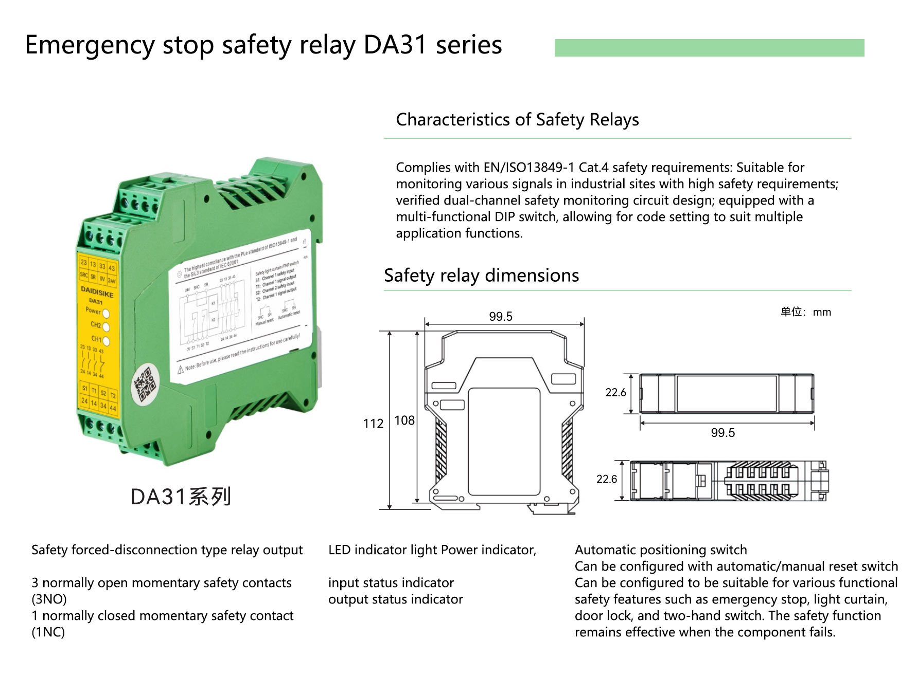
The standard DA31 variant covers dual-channel input (OSSD or NC contacts), two NO safety outputs at 6 A AC 15, one NC signalling contact, EDM input, manual or automatic reset, and 24 V DC supply. A delayed-output variant in the same family adds a time-delayed second output stage for stop category 1 applications. Wiring drawings, sample programs for typical line-PLC integrations and the type-test summary against EN ISO 13849-1 are available on the product page.
To talk through a specific safety architecture and whether the relay or PLC route fits, open a conversation at our contact page or look at the DA31 safety relay module, DAIDISIKE safety light curtain family and DLD safety laser scanner family to see the components that fit on the input and output sides of the safety chain.
10. Frequently asked questions
What is the difference between a safety relay and a safety PLC?
A safety relay is a fixed-function safety controller that takes a small number of safety inputs — typically an emergency stop, a safety light curtain pair, a safety door switch — and drives one or two pairs of safety outputs that cut power to the hazardous motion. Its logic is hardwired. A safety PLC is a programmable safety controller: the same inputs and outputs are available, but the logic between them is written in a safety-certified programming environment (typically a restricted subset of IEC 61131-3) and can implement several independent safety functions on the same hardware. The architectural difference is configurability, not safety level — both can reach PL e under ISO 13849-1 and SIL 3 under IEC 62061 when correctly applied.
When is a safety relay enough and when do I need a safety PLC?
A safety relay is enough when the machine has a small fixed number of safety functions that do not need to share state, the safety logic does not change over the life of the machine, the safety inputs and outputs together fit within a single device's channel count, and the start-up sequence is straightforward. A safety PLC starts paying back when the machine has more than three independent safety functions, when safety state needs to be shared across zones, when muting or PSDI sequencing is required, when the safety logic must change between recipes or products on the same machine, or when a daisy chain of relays would need more than three or four modules and a single programmable controller is both cheaper and easier to commission.
Can a single safety relay handle a light curtain and an emergency stop together?
Yes, in two ways. The simpler way is to use one safety relay with two separate input channels — one for the light curtain OSSD pair and one for the dual-channel emergency-stop button — wired so that either function de-energises the output. The cleaner way for non-trivial machines is two safety relays, one per safety function, with the outputs ORed at the contactor coil. The two-relay approach makes diagnostics easier (which function tripped is obvious from which relay's status LED is showing fault) and lets the operator reset the e-stop independently of the light curtain. On simple machines the single-relay approach is fine; on machines with more than ten cycles per minute and any operator interaction, the two-relay approach is worth the extra cost.
What is EDM and why does my safety relay need it?
EDM stands for External Device Monitoring. It is a feedback loop from the contactors that actually break power to the hazardous motion back into the safety relay's EDM input terminals. The feedback path is the normally-closed auxiliary contact of each contactor wired in series. When the safety relay commands the contactors to drop out, the NC contacts close; when the relay re-energises the outputs, those NC contacts must open before the relay will allow restart. If a contactor's main contacts have welded shut, its NC auxiliary will not close, EDM will not see the expected feedback, and the safety relay will block restart. EDM is what catches a single contactor failure before it becomes a runaway. Under ISO 13849-1, EDM is what lifts a Category 3 architecture to Category 4 (single fault detection).
What is the difference between manual and automatic reset?
Manual reset means the operator has to press a reset button to re-energise the safety outputs after the safety function has been satisfied (e-stop released, light curtain clear, door closed). Automatic reset means the safety outputs re-energise as soon as the inputs are clear, without any operator action. Manual reset is the default for any safety function that protects against operator access to a hazard — light curtains in front of presses, gates on robot cells, e-stops. Automatic reset is appropriate only for muting and presence-sensing where the cycle deliberately requires the safeguard to clear and re-arm without operator intervention, and only when ISO 13855 safety distance is preserved through the cycle. Wiring is different: manual reset uses an extra terminal for the reset button; automatic reset jumpers that terminal to 24 V.
How many safety relays can I daisy chain before a safety PLC makes more sense?
There is no hard rule but a practical ceiling is three to four. Beyond that, the wiring becomes hard to trace, response-time accumulation across cascaded outputs starts to matter, panel space pushes back, and the total cost of three or four safety relays plus the labour to wire them is close to a small safety PLC that does the same job with cleaner diagnostics. A safety PLC also gives non-safety reporting outputs to the line PLC almost for free, which a relay-based architecture has to add separately. We typically draw the line at four functions: at three or fewer safety functions a relay-per-function architecture is cleanest; at five or more a small safety PLC is the right answer; four is the grey zone.
Does a safety relay or safety PLC affect the response time of a safety light curtain?
Yes, and it counts directly in the ISO 13855 minimum-distance calculation. The total stopping time T used in S = K × T + C is the sum of the light curtain's OSSD response time, the safety relay or PLC's input-to-output response time, the contactor opening time and the machine's mechanical stopping time. A typical safety relay adds 10 to 30 ms; a small safety PLC adds 20 to 50 ms because it has to scan the safety program and IO; a networked safety PLC over a safety bus can add 50 to 100 ms depending on the bus update rate and the worst-case message timing. On a fast machine with a 30 mm resolution light curtain at 25 cycles per minute, the difference between a 15 ms relay and a 60 ms networked PLC moves the minimum safety distance from about 160 mm to about 240 mm — significant, and worth modelling before the panel is built.
Can a DAIDISIKE DA31 safety relay be used with any brand of safety light curtain?
The DA31 is designed to accept dual-channel OSSD inputs from any IEC 61496-2 Type 4 active opto-electronic protective device (AOPD), and similarly accepts dual-channel inputs from any IEC 60947-5-1 compliant emergency-stop button or safety door switch. The input electrical characteristics (PNP, 24 V DC nominal, internal pulse test rejection) are standard across the safety-light-curtain industry. The output side is two normally-open safety contacts (one or two NO depending on model variant) rated for typical contactor inrush, plus an EDM input. The DA31 has been used in commissioned installations with DAIDISIKE DQE, DQC, DQO, DQT and DQR light curtains and with the DLD safety laser scanner series, and the wiring is the same in each case — only the front-end sensor changes.
How much more expensive is a safety PLC than a safety relay?
On unit price alone, the smallest safety PLC starts at roughly four to six times the price of a DA31-class safety relay. But unit price is only half the picture. A safety relay's installed cost is essentially the device plus a few hours of wiring; a safety PLC's installed cost also includes the IO modules, the programming software licence, the safety programming labour, the validation labour and the documentation. Looked at as installed cost, a single safety relay lands at roughly one quarter the installed cost of the smallest safety PLC. The PLC route's cost gap closes as functions are added — by the time a relay-based design needs four or more cascaded modules plus the panel space and labour to wire them, a small safety PLC is in the same cost bracket and easier to commission.
What Performance Level and SIL can a safety relay reach under ISO 13849-1?
A correctly applied safety relay reaches the same safety integrity as a safety PLC — the device is not the limiting factor. Without External Device Monitoring (EDM) a safety relay tops out at Category 3 and PL d under ISO 13849-1. With EDM, and with the contactors wired so their feedback proves the output stage actually opened, the same relay reaches Category 4 and PL e. A DA31-class relay is type-approved against IEC 61508 SIL 3 and ISO 13849-1 PL e. The choice between a relay and a PLC is therefore about configurability, wiring effort and how many functions share the panel — not about the achievable Performance Level or SIL.
Do I need a safety PLC to mute a safety light curtain?
No. Muting and PSDI sequencing can be done either way. On a safety PLC the muting logic and its timing are defined in the safety program, which is the cleaner approach when several functions already live on the controller. Without a PLC, muting is handled by a dedicated muting relay (or muting-specific module) that times the muting-sensor inputs in hardware. A muting application is one of the clearest signals in the eight-question decision matrix that a programmable controller may earn its place — but a single muting set on an otherwise simple machine does not by itself require a PLC, and a muting relay is the right answer in that case. Whichever route is used, ISO 13855 safety distance must be preserved through the muted cycle.
What happens if I outgrow a safety relay panel after the machine is built?
This is the most common way the wrong early choice shows up. A relay-based design that started at three functions and has been incrementally extended to five usually ends up with a panel that is hard to read and a wiring loom that no two technicians remember the same way. The trigger is often a single new requirement — 'we need to add a second safety door but the relay panel is full.' At that point retro-fitting a safety PLC is a multi-day shutdown, not a quick change. This is why the selection guide draws the line at four functions: at three or fewer a relay-per-function architecture is cleanest, at five or more a small safety PLC is the right answer, and four is the grey zone where you should think about where the machine is heading over its life, not just where it is on day one.
Related reading
PL vs SIL — ISO 13849 and IEC 62061
The framework safety relays and safety PLCs are certified against.
OSSD wiring with EDM
How the OSSD pair and EDM loop physically wire through a safety relay.
Connecting safety light curtains to PLCs
Relay output vs OSSD solid-state output, and where each lands on the safety chain.
References
- ISO 13849-1:2023 — Safety-related parts of control systems — The PL framework safety relays and safety PLCs are evaluated against.
- IEC 62061:2021 — Functional safety of safety-related electrical, electronic and programmable electronic control systems — The SIL framework, applied in parallel with ISO 13849-1.
- ISO 13855:2024 — Positioning of safeguards with respect to the approach speeds of parts of the human body — The minimum-distance calculation that response time feeds into.
- IEC 61496-2:2020 — Active opto-electronic protective devices (light curtains) — The OSSD output standard the safety relay's input channels are designed for.
- IEC 60204-1:2016 — Safety of machinery. Electrical equipment of machines — Stop categories 0, 1 and 2 and the electrical-safety framework around the safety output stage.
- IEC 60947-5-1 — Low-voltage switchgear and controlgear. Control circuit devices and switching elements — Electrical requirements for emergency-stop devices, safety contactors and auxiliary mirror contacts used as EDM feedback.
- HSE — Work equipment and machinery — UK workplace-enforcement guidance referencing PUWER 1998 and SMSR 2008 for the legal context safety relays operate within.
This article is general engineering guidance, not a substitute for the standards themselves or for a qualified safety-engineering assessment of your specific machine. Always work from the current published text of ISO 13849-1, IEC 62061, ISO 13855 and IEC 60204-1, and a competent risk assessment for your specific application, when finalising a safety architecture.