
A single AMR is a tractable safety problem. The vehicle has a protective field in the direction of travel, the field tracks stopping distance through speed-dependent switching, the scanner is certified, the standards are clear. Get that right and the robot does not strike the person in front of it.
A fleet of AMRs is a different problem. The 2025–2026 wave of large deployments — fulfilment centres running well over a hundred vehicles in one building, automotive plants with AMR convoys feeding line-side, electronics factories blending conveyors and free-roaming robots — has surfaced safety questions that simply do not exist at five-vehicle scale. This article is about those.
What changes when you go from one vehicle to many
The vehicle-level safety case stays valid. What changes is everything around it.
- Vehicles can meet. Two AMRs at an intersection, two AMRs nose-to-nose in a narrow aisle, one AMR approaching another that is docked — none of these geometries exist with a single robot, and each one is a new safety scenario.
- Scanners share the optical environment. Two pulsed time-of-flight scanners looking into the same volume can interact. With one vehicle there is no peer; with fifty, peer interactions happen constantly.
- The fleet manager becomes load-bearing. Routing, zone allocation and intersection arbitration shift from heuristics to deterministic rules that the safety case starts to depend on.
- The wireless link matters. Whether the fleet rides on a private 5G slice, a Wi-Fi 6 deployment or older Wi-Fi 5 directly affects how quickly speed-zone changes propagate and how often vehicles fall back to safe-state.
- Emergent behaviour appears. Cascading slowdowns, clusters around a failed unit, oscillations between two valid routings — behaviours that only manifest at population scale.
Cross-vehicle scanner interference
A safety laser scanner measures distance by emitting a short laser pulse and timing the reflection. The fundamental assumption is that the pulses arriving at the receiver were emitted by the same scanner that is currently listening. With one scanner in a room, that assumption holds trivially. With ten scanners on ten different vehicles passing each other in the same aisle, there is a real probability that pulses from a peer arrive during another scanner’s receive window.
A misread interfering pulse can do one of two things. The benign outcome is that the device’s plausibility checks discard it — the pulse pattern does not match, the temporal signature is wrong, the measurement is rejected. The undesirable outcome is a nuisance stop, where the scanner treats noise as an object and triggers an unnecessary halt. The dangerous outcome — a peer pulse being misread as a closer return that masks a real obstacle — is what certified scanners are explicitly designed not to allow, through redundancy, plausibility and self-test under IEC 61496-3.
How modern scanners mitigate it
The mitigation strategies have converged on a few approaches, which are usually combined:
- Pulse-pattern modulation. Each scanner emits a modulated pulse pattern — varying inter-pulse timing, grouping, or coding — that it then expects to see echoed back. Pulses that do not match the expected pattern are discarded as noise.
- Scan-phase offset. The scanner offsets the angular phase of its scan when it detects interference, stepping the timing of when it looks in any given direction. Two adjacent scanners that drift into phase eventually drift out again, and interference becomes intermittent rather than sustained.
- Multi-pulse plausibility. The scanner requires multiple consecutive scans to agree before triggering a protective response, so a single stray pulse cannot cause a stop on its own. The trade-off is response time — more scans means more latency — which the design has to balance against the stopping-distance budget.
- Time-division and hardware sync. For tightly spaced scanners on the same vehicle, or fixed-infrastructure scanners at a single station, a hardware sync wire can ensure scanners take turns. Across a roaming fleet this is harder, but some deployments use wireless time-sync to keep populations of scanners loosely coordinated.
None of these techniques eliminates the residual probability of a nuisance stop, but they push the rate of a dangerous misread well below the failure-rate budget that PL d, Category 3 (or equivalent SIL 2) systems are designed to. The practical consequence on the floor: in a busy fleet you should expect occasional unexplained micro-stops on individual vehicles, and treat them as evidence the mitigation is working — not as defects to engineer out by removing the checks.
Speed-zone synchronisation through the fleet manager
The single-vehicle picture has the scanner switching field sets based on the vehicle’s measured speed and steering angle. The fleet picture adds a layer above that: the fleet manager knows which zone the vehicle is in — an open aisle, a pedestrian crossing, a slow zone in front of a workstation, a docking lane — and informs the vehicle accordingly.
In a typical deployment the fleet manager sends the vehicle a zone identifier over the wireless link. The vehicle’s control system uses that identifier to enforce a top speed, adjust route planning, and request a corresponding field-set change from the scanner via the safety controller. The scanner itself, however, does not blindly trust the wireless signal: its field set is only switched when the on-vehicle safety chain — the speed signal, the steering signal, and any discrete safety inputs — agrees the change is safe.
Why the wireless choice matters
Fleets running on older Wi-Fi see real consequences from the client-led roaming model: a vehicle handing off between access points can drop packets for hundreds of milliseconds, miss a zone transition, and either fall back to the conservative field set (a nuisance stop) or sit in a zone whose rules it no longer knows. Wi-Fi 6 reduces the roaming gap and improves deterministic scheduling within an access point. Private 5G, which a number of large 2025–2026 deployments have moved to specifically for AMR coordination, provides infrastructure-led handoff and predictable latency that more or less eliminates the roaming problem.
The point worth being clear on: none of this changes where the safety responsibility sits. A private 5G slice is not a safety-rated network in the IEC 61784-3 sense. It just reduces the rate at which the on-vehicle safety chain has to fall back to safe-state because it lost contact. Better wireless gives you a fleet that nuisance-stops less; it does not give you the ability to push safety functions off the vehicle and onto the network.
Blended traffic — people, AGVs, AMRs in the same aisle
Most real warehouse and factory floors are mixed. Pedestrians on foot, manually driven forklifts and tugger trains, a fleet of AMRs running fulfilment routes, a smaller fleet of AGVs serving fixed line-side stations, and occasionally a piece of mobile maintenance equipment all share the floor. The AMR’s own safety scanner protects against the AMR striking a person ahead of it. It does nothing about:
- A forklift striking the AMR (or a person near it).
- A pedestrian stepping out from between racking into the side of a moving AMR.
- Two AMRs meeting at a blind corner the fleet manager mis-allocated.
- A load on the AMR overhanging or extending above the scanner plane.
The competent response is to treat the floor as a system, not just the vehicle. Segregated lanes where the layout allows. Floor markings that match what the AMR routes actually do, so pedestrians have a reliable mental model. Warning fields tuned to give people real reaction time, not just stopping distance plus zero. Conservative speeds in shared zones, enforced by the fleet manager rather than left to local rules nobody checks. Good sightlines at intersections, supplemented by fixed-infrastructure scanners or light curtains where the vehicle-borne field cannot see far enough.
Intersection and crossing rules
Intersection management in a fleet is, almost always, the fleet manager’s job rather than the individual vehicle’s. The fleet manager treats each crossing as a resource: only one vehicle holds the resource at a time, others are queued, and the held vehicle releases the resource on exit. Priority is by route, time-in-queue, or sometimes payload urgency.
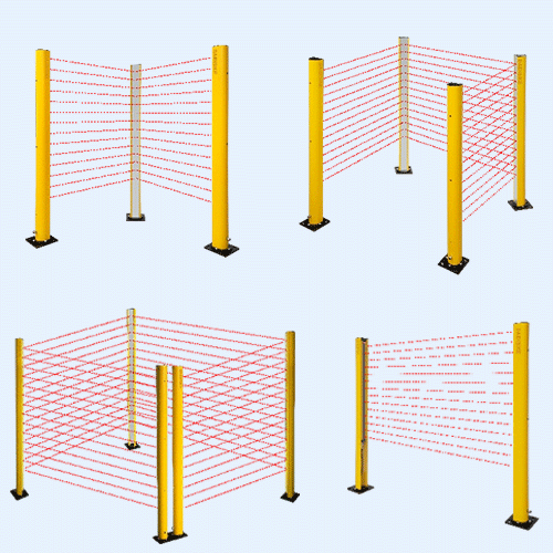
The on-vehicle safety scanner remains the last line. If a traffic rule is wrong, a vehicle is mis-positioned, or a pedestrian crosses the AMR lane unexpectedly, the scanner still triggers the protective stop. That last point matters: AMR routes that cross pedestrian walkways should not rely on traffic-rule discipline to keep people safe. Either segregate the route physically, or add fixed-infrastructure protection — an area scanner mounted to the building covering the crossing — that operates independently of any vehicle.
Dock and charge-station approaches
Docks and chargers are a special case because the vehicle is deliberately approaching a fixed object. A protective field sized for aisle travel would prevent the approach from ever completing — the dock face is well inside the field before the vehicle is in position. The pattern that works is a dedicated slow-approach field set:
- Activated only when the fleet manager confirms the vehicle is in a docking sequence, and the on-vehicle speed signal confirms speed is below a low-speed threshold (typically 0.3 m/s or so, but the threshold has to be justified by stopping-distance analysis at that speed).
- Sized for the short stopping distance at that low speed, with a minimal protective field forward of the bumper and a corresponding warning field beyond it.
- Geometry-aware: if the dock has known fixed obstacles in the field, those need to be either tolerated by the field shape or muted explicitly — never quietly turned off.
- De-activated automatically when the vehicle leaves the docking sequence, with the normal aisle field sets returning before any acceleration is permitted.
The most common shortcut at docks is to mute the protective field entirely once the vehicle is “close”. Do not do this. A person can still walk into the dock area, and the vehicle should still detect them, at least at short range.
The standards landscape
Fleet-scale safety sits under the same standards a single vehicle does, but they all read more demandingly:
| Standard | Fleet-relevant content |
|---|---|
| ISO 3691-4:2023 | Driverless industrial trucks and their systems. The 'system' explicitly includes supervisory control across multiple vehicles, traffic management, zone control and the safety functions that span them. |
| ANSI/RIA R15.08 | Industrial mobile robots in three parts. R15.08-2 addresses configuration and commissioning of a fleet at a site; R15.08-3 covers operation through life. Fleet-manager compliance is called out explicitly. |
| IEC 61496-3 | Electro-sensitive protective equipment, Part 3: AOPDDR (scanning devices). The interference-mitigation requirements live here. |
| ISO 13855 | Positioning of safeguards relative to approach speeds. Used for the protective-field sizing on every vehicle, including the slow-approach field at docks. |
| ANSI B11 mobile robot | B11.27 (mobile work platforms) and the ANSI B11 framework provide US machine-safety baselines that R15.08 sits on top of. |
The ANSI/RIA R15.08 framework is the one most often quoted on fleets, because Part 2 directly addresses the integration of a fleet at a site and Part 3 covers operation through the vehicles’ productive life. For more on R15.08’s three-part structure, see our companion guide on ANSI/RIA R15.08. For the single-vehicle fundamentals this article builds on, see AGV & AMR Safety Laser Scanners.
Single-vehicle vs fleet — what the engineer has to add
| Topic | Single vehicle | Fleet (10–200 AMRs) |
|---|---|---|
| Scanner interference | Negligible. | Expected; mitigated by modulation, phase offset, multi-pulse. |
| Field-set selection | Vehicle speed and steering only. | Vehicle speed and steering plus fleet-manager zone signal, cross-checked on the vehicle. |
| Wireless link | Operational only. | Operationally critical; private 5G or Wi-Fi 6 preferred for determinism. |
| Intersections | Not applicable. | Fleet-manager arbitration; on-vehicle scanner as last layer; fixed infra at pedestrian crossings. |
| Docks/chargers | Single slow-approach field set. | Same field-set logic, but with fleet-manager handshake to authorise the transition. |
| Validation | Test the vehicle. | Test the vehicle plus the population behaviour: cascades, clusters, recovery from failed units. |
| Standards focus | ISO 3691-4 vehicle clauses; IEC 61496-3. | ISO 3691-4 system clauses; ANSI/RIA R15.08-2 and -3; same IEC 61496-3 on each device. |
Validation: testing a fleet is not testing one robot fifty times
The most common validation mistake on fleet projects is to test individual vehicles thoroughly and then declare the fleet tested. It is not the same. A vehicle works as expected in isolation and still produces an emergent failure when fifty of its peers are interacting with the same traffic manager. The additional validation tasks a fleet brings include:
- Population-level scenarios. Run the fleet at the design population, not at a comfortable subset, and observe whether the safety functions still behave as intended — particularly under load surges, during shift handovers, and when one or two units fail and the rest re-route around them.
- Wireless failure injection. Deliberately drop access points, kill the fleet-manager link, or inject latency, and verify the vehicles fall back to safe-state cleanly and recover sensibly.
- Cross-vehicle interference observation.Monitor the rate of unexplained nuisance stops over a sustained period — days, not minutes. A sudden spike is usually a fleet of similar new scanners that have ended up phase-aligned and need their modulation patterns re-shuffled.
- Intersection load testing. Push the intersections to their throughput limits and verify the arbitration logic remains deterministic. Queueing fairness matters less than confirming there is no scenario in which two vehicles believe they hold the same crossing.
Where DAIDISIKE scanners fit, briefly and neutrally
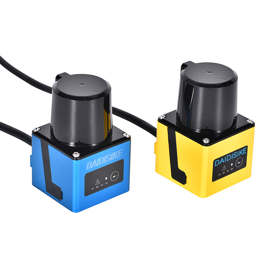
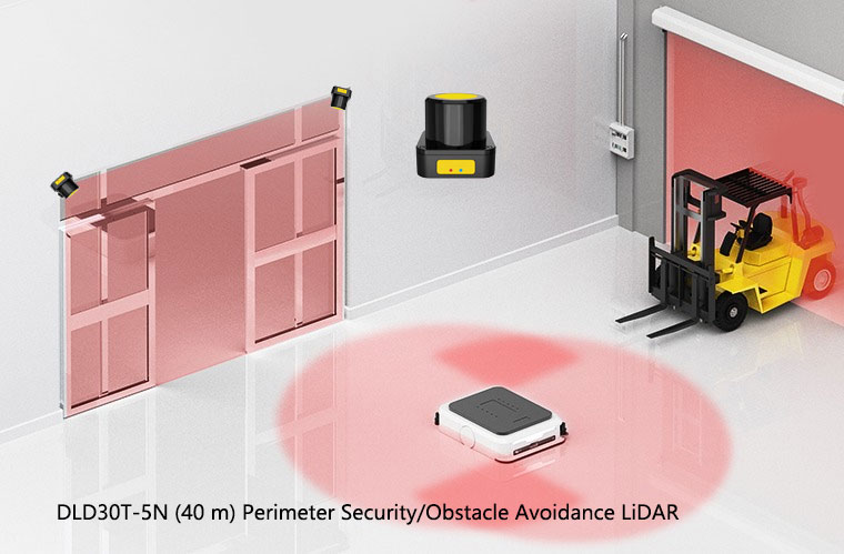
A practical note, since you may be on our site. DAIDISIKE supplies the DLD-series scanning LiDAR — the DLD05A3 (5 m), DLD20A5 (20 m), DLD30T-5N (40 m) and SDLD-05A (14 m) — covering the range and resolution envelopes typical of obstacle-avoidance and perimeter detection on AGVs and AMRs. In fleet deployments these devices sit alongside whatever certified safety scanner is doing the protective-stop function for personnel detection; the DLD devices contribute to navigation, situational awareness and peripheral detection, not the certified safety chain. For the full architecture of a fleet — navigation LiDAR, safety-rated scanner, fleet-manager interface and wireless stack — talk to our engineering team and we will be honest about which device does which job.
The bottom line
At fleet scale the safety problem moves outward from the vehicle. Scanners are no longer isolated devices; they share the optical environment with their peers and need interference mitigation that actually works in practice. The fleet manager stops being a piece of logistics software and becomes a safety-relevant element of the system, even if it is not itself safety-rated. Intersections, docks and pedestrian crossings need engineered rules, not goodwill. Validation has to cover population behaviour, not just individual-vehicle behaviour. ISO 3691-4:2023 and ANSI/RIA R15.08 already treat the fleet this way; the deployments that treat it the same way are the ones that stay out of the incident reports.
Related reading
Industrial Safety LiDAR — Complete Reference
The pillar reference for safety LiDAR scanners across industrial applications.
AGV & AMR Safety Laser Scanners
Single-vehicle fundamentals: protective fields, warning fields, speed-dependent switching.
ANSI/RIA R15.08 Explained
The North American mobile-robot standard, part-by-part, with fleet provisions.