This product is a trigger delay module. It can be used with voltages of 5V, 9V, 12V or 24V. It does not connect when the circuit is powered on. The trigger terminal can receive a high or low level trigger signal. After being triggered by this signal, the module conducts for a period of time and then disconnects. The delay time is calculated from the moment the level is applied; if the signal persists, the relay remains in the conducting state until the signal is removed and the delay ends.
This product is a trigger delay module that can be powered from 5V, 9V, 12V, 18V or 24V. Positive or negative trigger input polarities can be configured to make the module more flexible.
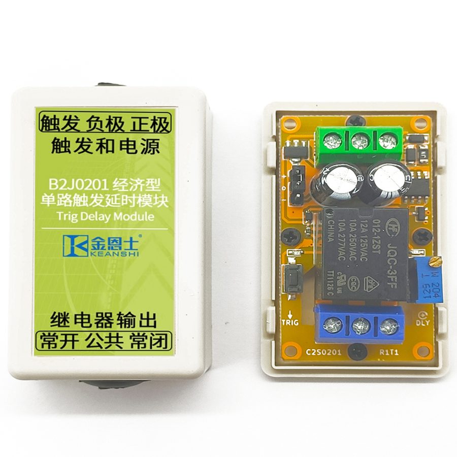
1.2 Structural Description
There are six screw terminals, one button, one potentiometer, one jumper and two LED indicators on the product. The description of each terminal and component are shown in the figure and table below.
Table 1-1 Product Front-side Marking
Name
No.
Meaning
Trigger terminal
0
With voltage threshold detection functionality. Green.
Normally open contact
1
The Normally Open (NO) contact of the relay. When the relay makes, this is connected to the common contact. Blue. For transistor output type products, this serves as the load ground.
Common contact
2
The COMmon (COM) contact of the relay. Blue. For transistor output type products, this serves as the load-side power supply ground.
Normally closed contact
3
The Normally Closed (NC) contact of the relay, when the relay breaks, this is connected to the common contact. Blue. For transistor output type, this serves as the common terminal of load and load-side supply.
Positive supply
4
Positive power supply. The typical current consumption when the relay makes is 40 mA. Green.
Negative supply
5
Negative power supply. The typical current consumption when the relay makes is 40 mA. Green.
Trigger button
6
The button for triggering the delay test. Black.
Adjusting knob
7
The knob for adjusting the delay time. Blue.
Action indicator
8
The indicator for the relay status. Blue.
Power indicator
9
The indicator for the power status. Green.
Level selection
10
The pin header for selecting the trigger level. Jump it at the upper position for high-level triggering and the lower position for low-level triggering.
1.3 Wiring Methods
The power supply terminals are directly connected to the DC power input. The normally open and normally closed relay terminals are connected according to the application needs and they are connected in series with the load and load power supply. The trigger terminal is connected to a voltage input to trigger the product according to the voltage change. For the transistor output type, the wiring diagram is described in 3.2. A typical wiring diagram of the relay output type is shown below.
1.4 Mechanical Dimensions
The mechanical dimensions of the product PCB are shown in the table below. The tolerance of all mechanical dimensions is 5%. All dimensions are in millimeters.
Table 1-2 PCB Mechanical Dimensions
Dimension
Value
PCB length
55
PCB width
30
Distance between upper and lower mounting holes
49
Distance between left and right mounting holes
24.5
Terminal spacing
5.08
This product comes with an optional miniature case. The mechanical dimensions of the case are shown in the figure below. All dimensions are in millimeters.
Chapter 2 Detailed Function Description
2.1 Delay Time Description
After the product is powered up, the relay is in break state. A high-level or a low-level trigger signal at the input triggers the module and then the relay makes. After an adjustable delay period, the relay will break. The countdown starts right after the trigger signal is applied; if the signal maintains, the relay will remain make until such signal is removed. This product has a potentiometer knob that is responsible for delay time adjustments. The adjustment range of the delay time is 2-30 seconds. Rotate the knob clockwise to increase the delay time and counterclockwise to decrease it. In addition to the trigger terminal, the trigger button on the product can also be used to trigger the delay sequence.
2.2 Trigger Level Configuration Description
The trigger level of this product is set by three-terminal pin header and a jumper cap. Set the jumper cap between "o" and "+" to use high level trigger. At this time, connect the trigger terminal to a positive voltage higher than 2V, which is the trigger delay. Set the jumper cap between "o" and "-" to use low level trigger. At this time, the trigger terminal is short-circuited to ground to start the delay.
Chapter 3 Modification Description
3.1 Preface
This product has the following modifications whose ordering numbers are in the form of B2J06[aa]R[b]T[c]M[dd]. The [aa] field is fixed as 01, as the module only has a single-channel version; the [b] field and [c] field are the main version number and sub-version number of the module respectively; the [dd] field determines the specific modification of the module. The module modification classes are mutually independent. If no specific requirement is designated when the product is shipped, the default option is the 12V relay output type, that is, M31. The specific meanings of the [dd] field are as follows.
Table 3-1 The Meanings of the [dd] Field
Digit
Description
Meaning
First
Supply voltage of the module
1: 5V supply type 2: 9V supply type 3: 12V supply type 4: 18V supply type 5: 24V supply type
Second
Output modes of the module
1: Relay output type 2: Transistor output type
3.2 Transistor Output Type Description
This version is connected to the circuit in open-drain mode as shown below. The transistor has a rated working voltage of 12-48V DC and a rated current of 10A. With a 10A freewheeling diode on the transistor, it can directly power an inductive load up to 10A. Certain loads e.g. filament lamps, mercury lamps exhibit a current spike during startup; some other loads e.g. heavy-duty motors, speakers and electromagnets emit extremely strong EMI during operation. Due to size limitations, it is impossible to implement good power line filters on this module; thus when the power of such loads exceed 1W it is recommended to use standalone power sources for the module and to place these loads as far as possible from the module, or the module may repeatedly reset when the load powers on.
Compared to relays, transistors are far more sensitive. Thus, when the module is being powered off, the internal states of the NE555 may become invalid; even if the delay is untriggered, the transistor may make for a moment and then break. This issue is nonexistent on the relay version, but must be accounted for when using transistor version modules, especially when the devices connected to the output may respond to such momentary pulses. A effective countermeasure is to use power sequencing: make sure that the product is powered on before the output is powered on, and that the output is powered off before the product is powered off.
Chapter 4 Electrical Specification Description
4.1 Normal Working Conditions
The normal working conditions of this module are shown in the table below. Only within this condition can the normal operation be guaranteed.
High-level selected: DC 0 - 30V Low-level selected: DC 0 - 5V
Output stress
Relay type: DC 30V or AC 0 - 220V, 8A Transistor type: DC 12 - 48V, 8A
Output isolated voltage
Relay type: Less than 250V Transistor type: Less than 130V
Operating temperature
-20 - 60℃
4.2 Absolute Maximum Ratings
The extreme conditions that this module can withstand are shown in the following table. Stresses at or above those listed here may permanently damage the module.
High-level selected: DC 50V Low-level selected: DC 5.3V
Output stress
Relay type: AC 250V, 10A Transistor type: DC 55V, 10A
Output isolating voltage
Relay type: DC 1000V, 60s (Type test only) Transistor type: DC 250V, 60s (Type test only)
Relay mechanical life
Relay type: More than 100,000 times (Actual life varies with load, > 10,000 times under heavy load)
Storage temperature
-40 - 85℃
4.3 Other Parameters and Certifications
The other parameters and certifications of this module are listed as follows. These parameters and certifications include electrostatic discharge, electrical fast transient and voltage surge tests that comply with the requirements of IEC61000-6-1-2016 (Edition 3.0, 2016-08) for light industry purposes. During all of these tests, the modules are powered by a well-grounded 12V supply and in active delay operation.
Table 4-3 Other Parameters and Certifications
Item
Details
Passing Criterion
Electrostatic discharge resistance
IEC61000-4-2: 1kV, discharge on all terminals
(A) module functions normally
Electrostatic discharge resistance
IEC61000-4-2: 2kV, discharge on all terminals
(C) module is not permanently damaged
Electrical fast transient resistance
IEC61000-4-4: 500V, 5kHz, 2min, applied to all terminals
(B) module functions normally, the delay time may slightly change
Electrical fast transient resistance
IEC61000-4-4: 1kV, 5kHz, 2min, applied to all terminals
(C) module is not permanently damaged
Surge resistance
IEC61000-4-5: 1kV voltage surge to ground, applied to power terminals (Guaranteed by design)
(C) module is not permanently damaged
Creepage distance
IEC60950-2: L/2N, Pollution degree 3, material category IIIa and IIIb, basic isolation from relay terminal to logic side, creepage distance above 6mm. The actual distance is above 9.2mm, which meets the requirements
Electrical clearance
IEC60950-2: H, Pollution degree 3, basic isolation from relay terminal to logic side, electrical clearance above 2mm. The actual distance is above 2.2mm, which meets the requirements
4.4 Notes on Reliability
This module is only qualified for commercial applications due to its miniature size, thus it is not recommended for formal industry situations with strong interference. Additional power filters and/or port filters are required if it must be used in this way. If such additional filters are not desired, a switching power supply with Electrical Fast Transient (EFT) resistance is required to power the module and the power supply cord must be shorter than 3m.
In addition, if the load exhibits current spikes during startup or emit extremely strong EMI during operation, it is recommended to use standalone power sources for the module and to place these loads as far as possible from the module, or the module may repeatedly reset when the load powers on, especially in cases where the power source has poor transient responsiveness or the 5V version is used.
During the test, the negative supply of the module is directly connected to the earth by default. The same connection should be made to obtain the stability index in the table above.
Chapter 5 Appendix
5.1 Typical Applications
The sound control light in a certain stairwell is required to turn on after the sound sensor detects the sound signal and turn off after the sound signal disappears for about 20 seconds. It is known that the sound sensor outputs a 5V high-level when it detects the sound signal.
5.1.1 Requirement Analysis
A relay input and an output are used in this application. The power supply voltage of the module is 12V generated by 220V AC mains power adapter, which can be completed by the B2J0201 M31 module.
5.1.2 Circuit Design
According to the above requirements, connect the circuit as shown in the figure: The trigger level is set by a three-terminal pin header and a jumper cap. Set the module jumper cap to the upper position and select high-level trigger in this application. The delay time is set by adjusting the knob on the potentiometer. Rotate the knob clockwise to increase the delay time and counterclockwise to decrease it. The adjustment range of the delay time is 2-30 seconds. In this application, we set it to 20 seconds.
Frequently Asked Questions
What supply voltages does the B2J0201 trigger delay module support?
The B2J0201 is offered in 5V, 9V, 12V, 18V and 24V DC versions, selected by the supply-voltage digit in the ordering number (the default shipped option is the 12V relay output type, M31). Each version has a defined working window — for example the 12V type operates from 11 to 14V DC with supply current under 50 mA.
How is the delay time adjusted and what is the range?
Delay is set with the on-board potentiometer knob, giving an adjustable range of 2 to 30 seconds. Rotate the knob clockwise to increase the delay and counterclockwise to decrease it. The countdown starts the moment the trigger level is applied; if the signal persists, the relay stays made until the signal is removed and the delay elapses.
How do I configure high-level versus low-level triggering?
Trigger polarity is set with a three-terminal pin header and a jumper cap. Place the cap between "o" and "+" for high-level trigger, then apply a positive voltage above 2V to the trigger terminal. Place it between "o" and "-" for low-level trigger, where shorting the trigger terminal to ground starts the delay. An on-board button can also trigger the sequence.
What is the difference between the relay output and transistor output versions?
The relay output type switches DC 30V or AC 0-220V up to 8A with mechanical contacts and over 100,000 operations. The transistor (open-drain) type is rated 12-48V DC at 10A with a freewheeling diode for inductive loads. Note that on power-off the transistor type can briefly conduct, so use power sequencing where momentary pulses matter.
Is the B2J0201 a safety relay, and what standards does it meet?
No — the B2J0201 is a general-purpose trigger delay relay module for commercial automation, not a forcibly-guided safety relay or safety PLC. It is tested for electrostatic discharge, electrical fast transient and surge per IEC 61000-6-1 (light industry). For strong-interference industrial use, add power or port filters, or use an EFT-resistant supply with a cord shorter than 3m.