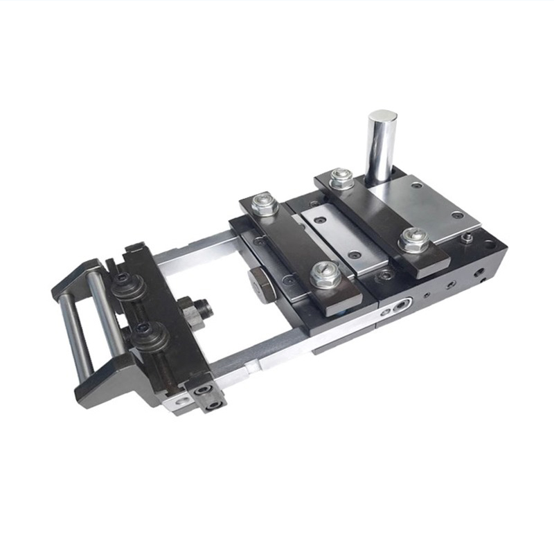
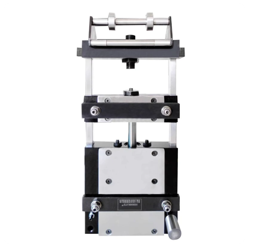
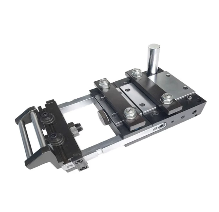
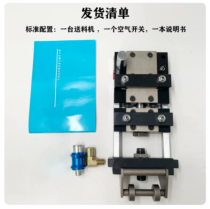
The air feeder (also called pneumatic feeder or press feeder) is automated equipment widely used in stamping to precisely feed metal coils/sheets into molds for punching, shearing, and forming. It features a compact pneumatic design, simple operation, and suitability for precision lines in electronics, hardware, and automotive production. Series include A, B, C, BX, CX, DX models, covering 0.3mm+ thicknesses, up to 250mm widths, adjustable lengths, and ±0.05mm accuracy. Key advantages: high wear resistance, no noise, light load, rapid displacement, relaxation solenoid support, and integration with straighteners/uncoilers for automated lines that cut costs and boost safety/stability.
The air feeder (also known as feeder, press feeder, air feeder) is an automated auxiliary equipment widely used in the stamping industry, mainly for precisely and continuously feeding metal coils or sheets into the press mold for punching, shearing, forming, and other operations. This series of products adopts pneumatic drive principle, with compact structure and simple operation, suitable for various precision stamping production lines, such as electronic parts, hardware accessories, automotive components, etc. The product series includes A series, B series, C series, BX series, CX series, DX series, and other models, covering a variety of material thicknesses from thin plates to thick plates (starting from 0.3MM), with a maximum feeding width of up to 250mm, adjustable feeding length, and support for high-precision feeding (accuracy up to ±0.05mm). The equipment features high wear resistance, no noise, light load, and rapid displacement, supporting continuous mold installation with relaxation solenoid valves to enhance automated processing efficiency. The air feeder can be linked with straighteners, uncoilers, and other equipment to form a complete stamping automation production line, significantly reducing labor costs and improving production safety and stability. According to professional terminology, this equipment belongs to "Pneumatic Feeder" or "Air Feeder", commonly used in "Stamping Press Feeding System", with core advantages in the rapid response of pneumatic cylinders and the reliability of material clamping.
Specification Table (English Translation)
The following is the specification table for the air feeder series compiled based on the provided data, covering parameters of main models, including maximum material width, feed length, thickness, fixed clamp force, movable clamp force, pull force, air consumption, weight, etc. The tables are divided into multiple series for easy comparison. Units: Width/Length (mm), Thickness (mm), Force (Kg), Air Consumption (L/min), Weight (Kg).
A/B/C Series Specification Table
Model
Max Material Width
Feed Length
Thickness
Speed (times/min)
Fixed Clamp Force
Movable Clamp Force
Pull Force (kg)
Air Consumption (L/min)
Weight (kg)
A50
50
50
1.9
280
64
120
25
50
4.3
A100
50
100
1.8
200
64
120
25
71
5.2
A150
50
150
1.5
160
64
120
25
80
6.1
A200
50
200
1.3
130
64
120
25
85
6.5
A250
50
250
1.1
110
64
120
25
90
7.7
B50
75
50
1.8
260
64
120
25
46
5.2
B100
75
100
1.7
190
64
120
25
67
6.2
B150
75
150
1.6
150
64
120
25
78
7.2
B200
75
200
1.2
110
64
120
25
77
8.2
B250
75
250
1.1
90
64
120
25
78
9.2
C50
100
50
1.7
210
64
120
25
37
6
C100
100
100
1.5
160
64
120
25
56
7
C150
100
150
1.4
120
64
120
25
68
8.2
C200
100
200
1.3
90
64
120
25
63
9.4
C250
100
250
1.2
80
64
120
25
56
7
BX/CX/DX Series Specification Table
Model
Max Material Width
Feed Length
Thickness
Speed (times/min)
Fixed Clamp Force
Movable Clamp Force
Pull Force (kg)
Air Consumption (L/min)
Weight (kg)
BX50
75
50
2.2
260
70
158
41
64
6.6
BX100
75
100
2
180
70
158
41
92
8.1
BX150
75
150
1.8
150
70
158
41
115
9.6
BX200
75
200
1.6
120
70
158
41
122
11.1
BX250
75
250
1.5
90
70
158
41
115
12.6
CX50
100
50
1.5
250
70
158
41
61
7.3
CX100
100
100
1.5
170
70
158
41
87
8.8
CX150
100
150
1.7
140
70
158
41
107
10.2
CX200
100
200
1.6
140
70
158
41
115
13.1
CX250
100
250
1.5
230
70
158
41
59
13.1
DX50
150
50
1.6
230
70
158
41
59
10
DX100
150
100
1.4
160
70
158
41
82
11.6
DX150
150
150
1.2
130
70
158
41
100
13.1
DX200
150
200
1.2
130
70
158
41
102
14.6
DX250
150
250
1
100
70
158
41
103
16.1
Technical Parameters (English Translation)
The technical parameters of the air feeder include the following key indicators (based on professional terms such as "Feed Length", "Material Thickness", "Clamp Force", etc.):
Max Material Width: 50-250mm, suitable for different widths of metal coils.
Air Consumption: 37-115 L/min, depending on the model, using standard air pressure of 0.5-0.8MPa.
Weight: 4.3-16.1 Kg, lightweight design for easy installation.
Accuracy: ±0.05mm (in continuous mold mode), suitable for precision stamping.
Speed: Up to 400 times/min, synchronized with the press.
Power Supply: No electricity required, only compressed air source.
Installation Method: Side or top mounting, supporting linkage with press, equipped with linear bearings for no noise and high wear resistance.
Safety Features: Installed with relaxation solenoid valve to prevent material jamming; overload protection.
Applicable Materials: Metal sheets, aluminum alloys, stainless steel, etc.
Environmental Requirements: Operating temperature 0-50°C, humidity <80%, clean air source without oil or water.
Working Principle (English Translation)
The working principle of the air feeder is based on a pneumatic control system, using compressed air as the power source, achieving automatic clamping, feeding, and releasing cycles of materials through cylinders and solenoid valves, synchronized with the press operation. The specific process is as follows:
Preparation Stage: Material enters the feeder's inlet from the uncoiler or straightener. The air source provides 0.5-0.8MPa compressed air, entering the cylinder for drive preparation.
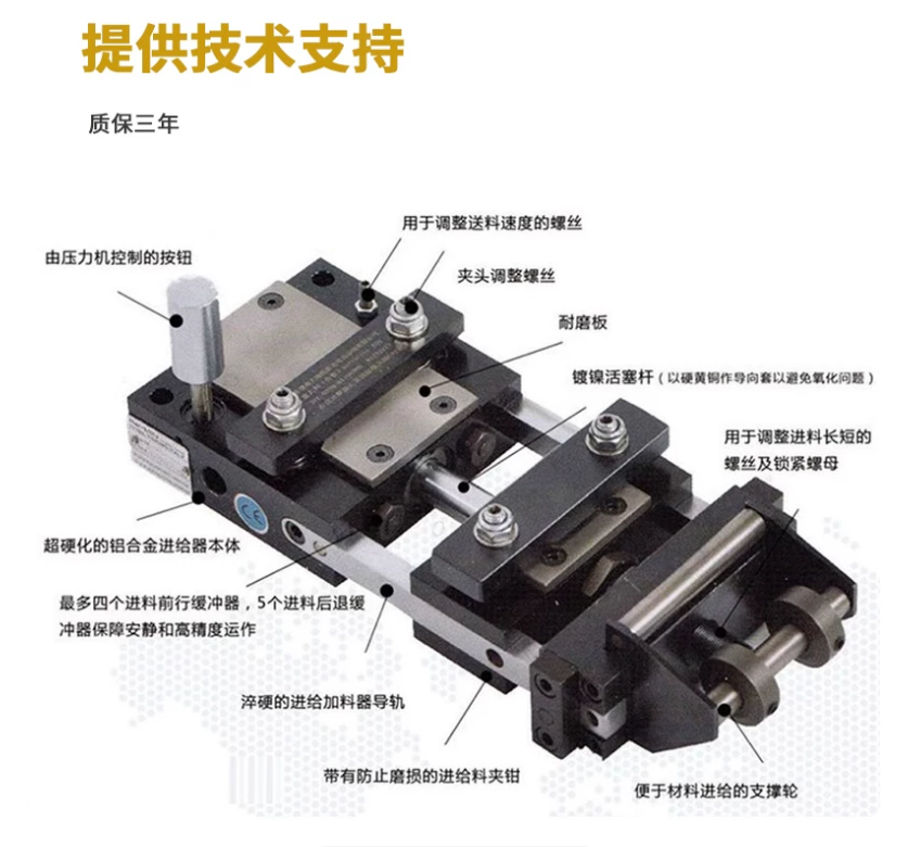
Clamping Stage: When the press slider rises to the top dead center, the solenoid valve opens, and compressed air pushes the fixed clamp and movable clamp to grip the material. The fixed clamp force ensures stability, and the movable clamp force provides traction power.
Feeding Stage: The cylinder pushes the feed arm forward, feeding the material into the press mold according to the set length. The support uses linear bearings to ensure rapid displacement, no noise, and high wear resistance. Feeding accuracy is controlled by the adjustment valve, up to ±0.05mm.
Releasing Stage: When the press slider descends to start stamping, the solenoid valve switches, and the cylinder releases the clamps, loosening the material. At the same time, the relaxation solenoid valve activates to prevent material rebound or jamming.
Return Stage: The cylinder resets, preparing for the next cycle. The entire process is linked with the press's cam signal to achieve automated continuous feeding.
This principle is suitable for automated processing, especially for new strong models for thicker materials. Maintenance is simple, requiring only regular checks of the air source and bearing lubrication. In professional terms, this is an "Intermittent Feeding Mechanism", emphasizing the rapid response of pneumatic cylinders and light load characteristics.
Frequently Asked Questions
What is a pneumatic (air) feeder and how does it differ from an NC servo feeder?
A pneumatic feeder uses compressed air (0.5–0.8 MPa) and cylinders to clamp, advance and release metal coil into a stamping press, with no electricity required. It is light, low-noise and cost-effective for short, fixed feed strokes. An NC servo feeder uses a servo motor for programmable, longer and more flexible feed lengths. For high-speed, short-pitch stamping, the air feeder remains a popular, economical choice.
What material thickness, width and feed length does the A50A100BX150 support?
The A/B/C and BX/CX/DX series handle metal strip from 0.3 mm upward, maximum material widths of 50–250 mm and adjustable feed lengths of 50–250 mm. Thicker plates use the reinforced BX/CX/DX models, which provide higher clamp and pull forces. Always match the model to your coil width, thickness and stroke pitch for reliable feeding.
How accurate and how fast is this air feeder?
Feeding accuracy reaches ±0.05 mm in continuous-die (progressive) mode, controlled by the adjustment valve and linear-bearing guidance. Speed reaches up to 400 strokes per minute when synchronized with the press cam signal. This combination suits precision stamping of electronic parts, hardware accessories and automotive components where repeatable pitch is critical.
What air supply and connections does the pneumatic feeder need?
It needs a clean, oil- and water-free compressed-air source at 0.5–0.8 MPa; no electrical power is required for the feeder itself. Air consumption ranges from about 37 to 115 L/min depending on model. A relaxation solenoid valve is supported for progressive dies, and the unit links to the press cam signal for automated intermittent feeding.
Can the air feeder integrate into a full stamping automation line?
Yes. The feeder links with straighteners and uncoilers to form a complete coil-feeding line for punch-press automation. Side or top mounting is supported, with linear bearings for quiet, wear-resistant operation and overload protection. This reduces labor cost and improves the safety and stability of the stamping press feeding system.