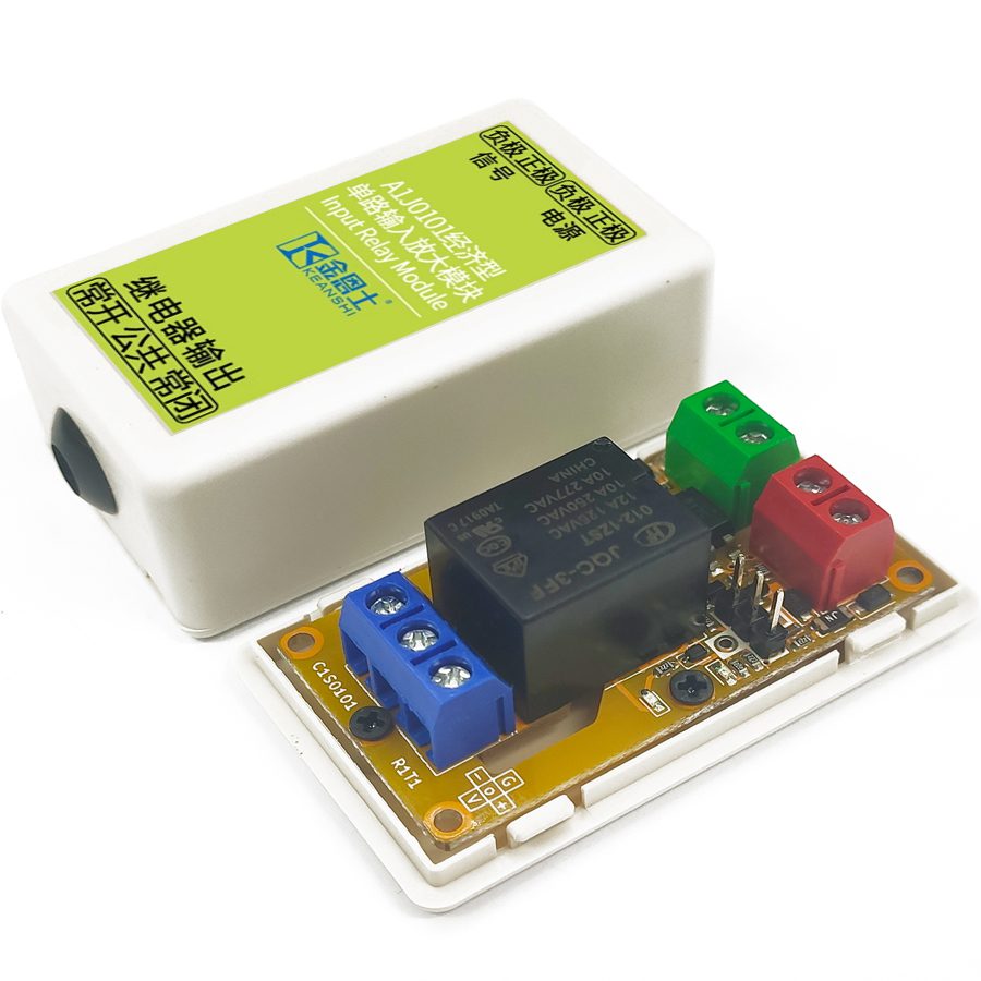
This product is an optocoupler isolated input amplification module. It can be used in conjunction with 5V, 9V, 12V or 24V voltages. After the product is powered on, if a voltage signal is applied to the optocoupler end, the relay will be connected; if the signal is removed, the relay will be disconnected. The polarity of the input signal can be selected; it can be set to be attracted when the input is high or when the input is low.
If there is a valid signal connected to the optocoupler terminal of this product, the relay will make, and if there is no signal, the relay will break. The input polarity of the signal may be inverted, or the relay may be configured to be normally open or normally closed on power up.
Input Polarity Setting Description
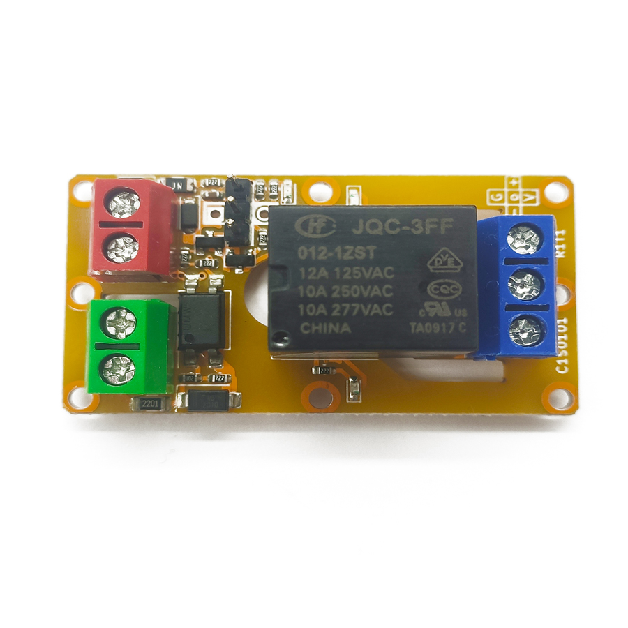
Jump the jumper cap between "o" and "+" to select high-level operation, i.e., the relay will make when the optocoupler terminal perceives a high-level and break when the optocoupler terminal perceives a low-level. Jump the jumper cap between "o" and "-" to select low-level operation, i.e., the relay will make when the optocoupler terminal perceives a low-level and break when the optocoupler terminal perceives a high-level. When the product is configured for low-level operation, the input status indicator will keep illuminated.
The relay of this product may also be configured to a constant make or break, independent of the optocoupler signal. Jumping the jumper cap between "o" and "V" permanently makes the relay, and jumping the jumper cap between "o" and "G" permanently breaks the relay. The "V" and "G" terminals are shipped unpopulated by default and need to be soldered when required.
Discrete Module Usage Description
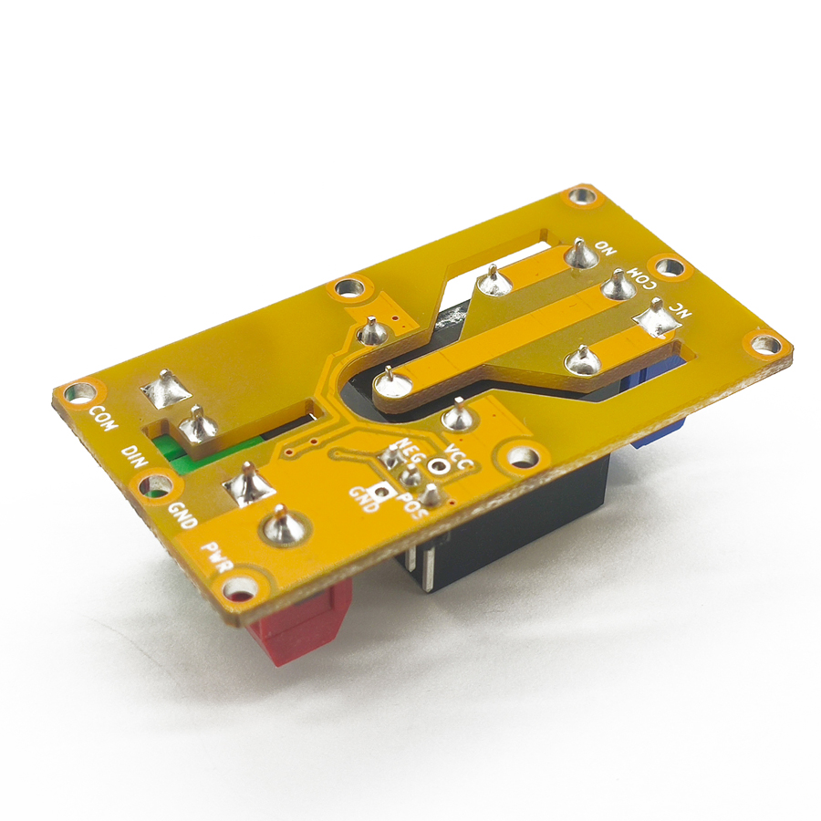
The optocoupler and relay terminals of this product may be used separately, i.e., as one standalone optocoupler isolated input and one standalone relay isolated output. When using the product in this way, the jumper cap on the product needs to be removed. The functions of the five jumper terminals on the product are listed below. These five terminals may be used according to specific applications in a flexible manner.
Terminal Name
Function
V
Connects directly to the power supply terminal of the product, as a high-level reference voltage.
G
Connects directly to the ground terminal of the product, as a low-level reference voltage.
+
When there is a high-level at the optocoupler terminal, the output is the same high-level as the supply voltage, otherwise it is low-level.
-
When there is a low-level at the optocoupler terminal, the output is the same high-level as the supply voltage, otherwise it is low-level.
o
If connected to a high-level above 2V, the relay will make; if connected to a low-level, the relay will break.
Product Variants
This product has the following modifications whose ordering numbers are in the form of C1S01[aa]R[b]T[c]M[dd]. The [aa] field is fixed as 01, as the module only has a single-channel version; the [b] field and [c] field are the main version number and sub-version number of the module respectively; the [dd] field determines the specific modification of the module. The module modification classes are mutually independent. If no specific requirement is designated when the product is shipped, the default option is the 12V relay output type, i.e., M31. The specific meanings of the [dd] field are as follows.
Digit
Description
Meaning
First
Supply voltage of the module
1: 5V supply type 2: 9V supply type 3: 12V supply type 4: 18V supply type 5: 24V supply type
Second
Output modes of the module
1: Relay output type 2: Transistor output type
Transistor Output Type Description
This version is connected to the circuit in open-drain mode. The transistor has a rated working voltage of 12-48V DC and a rated current of 10A. With a 10A freewheeling diode on the transistor, it can directly power an inductive load up to 10A. Compared to relays, transistors are far more sensitive. Thus, when the module is being powered on or off and the input is left unconnected, the transistor may make for a moment and then break. This issue is nonexistent on the relay version but must be accounted for when using transistor version modules, especially when the devices connected to the output may respond to such momentary pulses. An effective countermeasure is to use power sequencing: ensure that the product is powered on before the output is powered on, and that the output is powered off before the product is powered off.
Electrical Specification Description
Normal Working Conditions
The normal working conditions of this module are shown in the table below. Only within these conditions can normal operation be guaranteed.
Relay type: DC 30V or AC 0 - 220V, 8A Transistor type: DC 12 - 48V, 8A
Input isolating voltage
Less than 250V
Output isolating voltage
Relay type: Less than 250V Transistor type: Less than 130V
Operating temperature
-20 - 60℃
Absolute Maximum Ratings
The extreme conditions that this module can withstand are shown in the following table. Stresses at or above those listed here may permanently damage the module.
Relay type: AC 250V, 10A Transistor type: DC 55V, 10A
Input isolating voltage
DC 1000V, 60s (Type test only)
Output isolating voltage
Relay type: DC 1000V, 60s (Type test only) Transistor type: DC 250V, 60s (Type test only)
Relay mechanical life
Relay type: More than 100,000 times (Actual life varies with load, > 10,000 times under heavy load)
Storage temperature
-40 - 85℃
Other Parameters and Certifications
The other parameters and certifications of this module are listed as follows. These parameters and certifications include electrostatic discharge, electrical fast transient, and voltage surge tests that comply with the requirements of IEC61000-6-2-2016 (Edition 3.0, 2016-08) for basic industry purposes. During all of these tests, the modules are powered by a well-grounded 12V supply and in active delay operation.
Item
Details
Passing Criterion
Electrostatic discharge resistance
IEC61000-4-2: 6kV, discharge on all terminals.
(A) Module functions normally.
Electrical fast transient resistance
IEC61000-4-4: 2kV, 5kHz, 2min, applied to all terminals.
(B) Module functions normally, the relay may jitter to a certain degree.
Electrical fast transient resistance
IEC61000-4-4: 4kV, 5kHz, 2min, applied to all terminals.
(C) Module is not permanently damaged.
Surge resistance
IEC61000-4-5: 1kV voltage surge to ground, applied to power terminals. (Guaranteed by design)
(C) Module is not permanently damaged.
Creepage distance
Pollution degree 3, material category IIIa & IIIb, basic isolation from relay terminal to logic side, creepage distance above 6mm.
The actual distance is above 6.05mm, which meets the requirements.
Electrical clearance
Pollution degree 3, basic isolation from relay terminal to logic side, electrical clearance above 2mm.
The actual distance is above 2.2mm, which meets the requirements.
This product has enhanced stability, thus well resists interferences in general industrial environments, and may be used as a general product in industrial applications. If additional stability is still required, a switching power supply with Electrical Fast Transient (EFT) resistance or a supply line filter is required to power the product, and the power supply cord must be shorter than 3m. During all tests, the negative supply of the product is directly connected to the earth by default. The same connection should be made to obtain the reliability performance in the table above.
Legal Statement
The company reserves the right to further modify, upgrade, and amend the product and its manuals without notifications. The user should confirm that the information is complete and up-to-date before placing an order. The company is not responsible for the specific application of the customer and only guarantees that the module functions properly under normal working conditions. This product may be protected by one or more patents or other forms of intellectual properties and may contain third-party intellectual properties; the use of this product does not authorize the user to the patented technologies and intellectual properties contained in this product, nor does it authorize the user to the potentially involved third-party intellectual properties, either expressly or implicitly. Reproduction of this technical manual in part or in whole is allowed only on the premise of maintaining the integrity of the technical data in this technical manual and this legal statement. The company is not responsible for such copies and their uses. This product is not intended for purposes where failure or faulty operations may cause major injuries or major property damages, such as life support equipment or nuclear industry equipment, even if the company has been explicitly informed or implied that the customer may apply the product to such uses. If the customer applies this product to the above-mentioned uses, the company is not responsible for the associated losses caused by the failure of the product. The company does not take responsibility for the user configurations of the product and only guarantees the correct operation of the product according to these configurations. Nor does the company guarantee that the specific configuration is suitable for a specific purpose. The company shall not be held liable for any losses in cases where the user configurations do not fit the specific purpose.
Frequently Asked Questions
Is the A1J0101 a safety relay or a standard signal-isolation relay module?
The A1J0101 is a general-purpose optocoupler-isolated input amplifier with relay or transistor output, not a forcibly-guided safety relay with EDM feedback. Use it for signal isolation, level shifting and load switching in industrial control. For a stop function requiring a safety PLC or safety relay vs safety PLC selection, use a dedicated safety-rated device instead.
What supply voltages does the A1J0101 support?
The module works with 5V, 9V, 12V, 18V or 24V DC, selected by the model code (M11–M51). The default shipped option is the 12V relay output type (M31). Each voltage variant has a defined normal operating window — for example 12V DC accepts 11–14V — so order the variant that matches your control supply rather than relying on field adjustment.
How do I set the input polarity so the relay makes on a high or low signal?
Move the jumper cap on the DIN-rail module between the 'o' terminal and '+' for high-level operation, so the relay makes on a high input and breaks on a low input. Jump 'o' to '-' for low-level operation, where the relay makes on a low input. In low-level mode the input status indicator stays illuminated.
What load can the relay and transistor outputs switch?
The relay output type switches DC 30V or AC 0–220V at 8A under normal conditions, with an absolute maximum of AC 250V, 10A. The transistor (open-drain) type is rated 12–48V DC, 10A and includes a 10A freewheeling diode so it can directly drive an inductive load. Relay mechanical life exceeds 100,000 operations under light load.
Why does the transistor-output version pulse briefly at power-up?
Transistors are far more sensitive than relays, so when the module is powered on or off with the input left unconnected, the open-drain transistor may make momentarily then break. Avoid this with power sequencing: power the module on before its output, and power the output off before the module. The relay-output version does not have this behaviour.