
In short: ANSI/RIA R15.08 is the US-led safety standard for industrial mobile robots, published by the Association for Advancing Automation (A3). Part 1 (R15.08-1-2020) covers the manufacturer of the IMR. Part 2 (R15.08-2-2023) covers the system integrator deploying the IMR or fleet on site. Part 3 covers the end user during productive life. It is the North American counterpart to ISO 3691-4, with broader coverage of mobile manipulators and a sharper split of responsibility. Personnel-detection functions typically resolve to PL d / Category 3 and require a certified safety laser scanner, not a navigation LiDAR.
Walk any large US distribution centre in 2026 and you will see something that did not exist at scale ten years ago: dozens of autonomous mobile robots threading between people, racks, and conveyors. Industry trackers put the deployed US fleet north of forty thousand AMRs by mid-2025, with manufacturing accounting for the single largest end-use share. That growth is the reason R15.08 exists, and the reason buyers, integrators and EHS managers now have to read it.
R15.08 is not a long-standing document — Part 1 was first published in 2020. It is also not a finished one. Part 2 landed in late 2023; Part 3 was working toward publication through 2025. That timeline alone tells you the standard is being built while the industry it governs is already in production. This article walks through the three parts the way we would explain them to a customer specifying safety LiDAR scanners for a US deployment, with honest comparisons to ISO 3691-4 where they help.
What R15.08 actually is, and who publishes it
R15.08 is an American National Standard developed by the Association for Advancing Automation (A3) — the trade body that absorbed the Robotic Industries Association (RIA) and is now the secretariat for the R15 robot-safety committee. You will see the older “ANSI/RIA R15.08” prefix on Part 1 and the newer “ANSI/A3 R15.08” prefix on later parts; the rename is administrative, not technical.
The standard covers what it calls an Industrial Mobile Robot — a deliberately broad term that captures classical AGVs (predefined paths, magnetic or wire guidance), autonomous AMRs (free navigation with onboard obstacle avoidance), and mobile manipulators (a robot arm mounted on a mobile base). That last category is the one that exposes a gap in older documents: a mobile manipulator is both a mobile robot under ISO 3691-4 and an industrial robot under R15.06, and the two documents do not always say the same thing. R15.08 is, in part, an attempt to close that seam.
What R15.08 does not cover: consumer or household robots, undersea, military, space, surgical or rehabilitation robots, and personal mobility devices. If your vehicle is purely a powered industrial truck operated by a driver, ANSI/ITSDF B56.5 still applies; R15.08 picks up where the driver is removed.
Part 1 — Requirements for the Industrial Mobile Robot (the manufacturer)
ANSI/RIA R15.08-1-2020 is the part that the AMR builder has to satisfy at the factory gate. It sets out the safety requirements for the vehicle itself, before any application configuration. The headline obligations include:
- A safety-related control system that meets a Performance Level justified by risk assessment per ISO 13849-1 — PL d / Category 3 is the typical outcome for personnel-detection and emergency-stop functions.
- Protective stop initiated by certified safeguarding (typically an IEC 61496-3 safety laser scanner) covering the direction of travel.
- Speed-dependent protective fields: as the vehicle slows, the field can shrink in a defined, validated way; as it accelerates the field has to expand before motion begins.
- Emergency stop devices accessible to people in the operating environment, not just the operator station, and meeting ISO 13850.
- Stability requirements, including handling slopes, payload shift and ramps without tipping under specified conditions.
- Information for use: the manufacturer hands the integrator a documented envelope of conditions the IMR is safe in. Operating outside that envelope is the integrator’s problem.
That last point is the philosophical core of Part 1. The manufacturer does not deliver a safe robot; the manufacturer delivers a robot that is safe when used in accordance with the information for use. The integrator and the user have to stay inside that envelope, and Parts 2 and 3 are where the envelope is policed.
Part 2 — Requirements for IMR systems and applications (the integrator)
ANSI/A3 R15.08-2-2023 is the part most plant engineers underestimate. It addresses what happens when one or more IMRs are integrated into an actual site: the layout, the fleet manager, the interactions with people and with other equipment, and the configuration of safety functions to the real environment.
The big shifts that Part 2 introduces are:
- Application risk assessment. The vehicle’s factory risk assessment is a starting point. The integrator has to redo the assessment for the deployed environment — aisle widths, mixed pedestrian and vehicle traffic, dock doors, interactions with conveyors and stationary robots.
- Protective field definition. The safety scanner’s field sets are configured against the actual layout, with speed-dependent switching validated in situ. A scanner shipped from the factory with a generic field cannot pass a Part 2 review.
- Fleet and interaction safety. Two IMRs passing each other, or an IMR docking into a fixed station, are interaction hazards Part 1 cannot anticipate. Part 2 puts them on the integrator’s plate.
- Validation and acceptance. The integrator has to demonstrate the safety functions perform as designed in the deployed environment, document the results, and hand the dossier to the user.
In our experience, Part 2 is where most projects gain or lose their safety margin. A capable IMR from a top-tier manufacturer can still be unsafe if the integrator copies a generic protective field across thirty vehicles without re-validating against the actual aisle geometry. The reverse is also true: a midrange platform integrated carefully will outperform a premium platform deployed sloppily.
Part 3 — Requirements for the User (lifetime operation)
Part 3 covers the user — the operating company — during the productive life of the IMR system. Publication has been on the A3 work programme since 2024, with the document targeted for late 2025; readers should check the A3 store for the current edition status before quoting clauses.
Conceptually, Part 3 is the operational counterpart to Part 2. Where Part 2 closes with site acceptance, Part 3 opens with ongoing responsibility. That includes change management when the floor layout is modified, training of staff who work around the robots, periodic checks of the safety functions (including stopping distance, field integrity, e-stop function), and documented re-validation when the operating envelope changes — new payload sizes, new aisles, a different shift pattern that mixes more pedestrians.
The user-side gap that Part 3 is trying to close is real. Plants typically have mature programmes for stationary machine guarding — an annual check of every light curtain, a recorded response-time test — but the equivalent discipline around mobile robots is younger and less formal. A curtain stays where you put it; an AMR roams, and the floor it roams across changes more often than the curtain’s mounting hardware does.
R15.08 and ISO 3691-4 side by side
Both standards are widely cited in mobile-robot RFQs. The quick comparison below covers the points buyers ask about most often. It is a working summary, not a substitute for reading either document.
| Topic | ANSI/RIA & A3 R15.08 | ISO 3691-4:2023 |
|---|---|---|
| Primary region | United States / North America | International; basis for CE in EU |
| Publishing body | Association for Advancing Automation (A3) / ANSI | ISO TC 110 / SC 2 |
| Scope | Industrial Mobile Robots: AGV, AMR, mobile manipulator | Driverless industrial trucks and their systems |
| Structure | 3 parts: manufacturer, system integrator, user | Single document; annexes for specific equipment |
| Mobile manipulators | Explicitly addressed | Outside primary scope; rely on R15.06 / ISO 10218 |
| Personnel detection PL | Risk-assessed; PL d Cat 3 typical forward direction | Table 1 lists minimum PL by function (PL d typical) |
| Application/user duties | Detailed in Parts 2 and 3 | Less developed; user duties spread thinner |
| Legal status | Voluntary; OSHA general duty applies | Voluntary; aligned with EU Machinery Regulation expectations |
The honest reading is that the two standards are converging rather than diverging on the technical fundamentals — field-of-view, protective stops, PL ratings — while R15.08 carries more weight on the integration and operational phases. Vendors shipping globally tend to engineer to satisfy both, and that is the safest path for a buyer planning North American and European sites from one platform.
What R15.08 means for safety LiDAR scanner selection
The single specification question buyers ask us most often is whether their navigation LiDAR can double as a safety device. Short answer: no. R15.08 leans on IEC 61496-3 for active opto-electronic protective devices with scanning functions, and that means a Type 3 certified safety laser scanner with the diagnostic coverage, dual-channel output (OSSD), and fault-detection architecture needed to sit in a PL d Category 3 chain. A navigation LiDAR does none of that. It can be excellent at mapping and obstacle avoidance for path planning, and it will still be present on most modern AMRs alongside the safety scanner — the two devices do different jobs.
The practical scanner-selection questions that follow from R15.08 are:
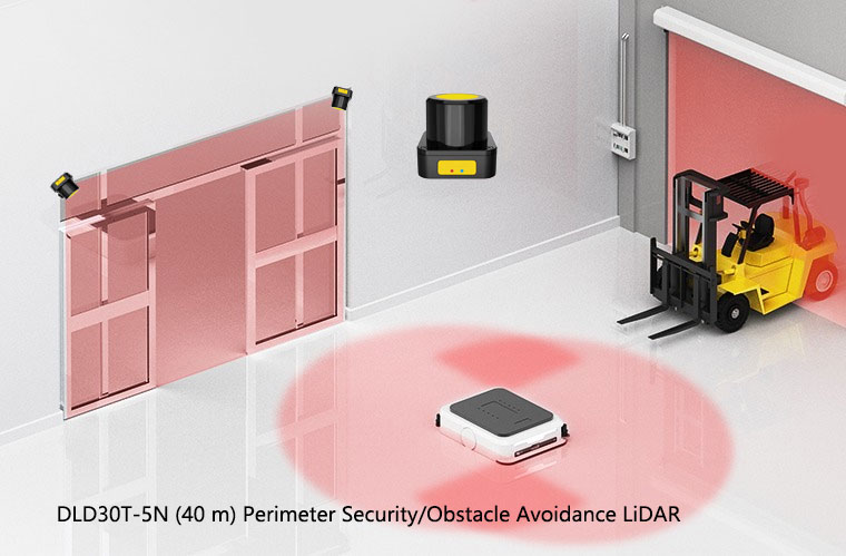
- Range matched to vehicle speed. Faster vehicles need longer protective fields to give the brake time it needs; the ISO 13855-style stopping calculation drives the answer. Our short-range scanner option, the DLD05A3 with 5 m range, suits compact AMRs in tight aisles; the DLD20A5 at 20 m fits faster tow tractors; the DLD30T-5N at 40 m is more often a perimeter scanner than an onboard device.
- Multiple switchable field sets. Part 1 and Part 2 both require speed-dependent field switching. The scanner needs the field-set capacity and the safe input encoding to do this in a validated way.
- Warning field plus protective field. The warning field slows the vehicle; the protective field stops it. Done well, this combination keeps throughput up while keeping incidents down. Done badly, the warning field is too small to make the protective stop a soft event.
- Mounting that meets the standard. The scanner has to see the legs of a standing person at the front of the vehicle and not be blinded by mirrored or absorbent surfaces in the operating environment. That is an integrator job under Part 2, not a manufacturer job under Part 1.
The mistakes we see on R15.08 projects
Treating Part 1 conformance as the whole answer. A vendor states the IMR is R15.08-1 compliant, and the buyer assumes the deployment is safe. It is not, until Part 2 has been executed at the site. The integration step is where most actual incidents originate.
Mixing up navigation LiDAR and safety LiDAR in the BOM. A line item that says “LiDAR sensor” can hide either kind. We have seen procurement teams substitute a cheaper navigation unit, only to be caught at safety validation. Specify the part number and the IEC 61496-3 Type explicitly.
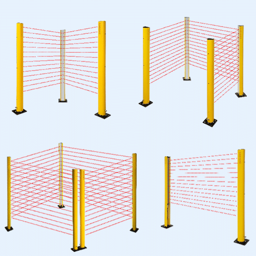
Forgetting the fixed-station side of the deployment. AMRs dock into pick stations, conveyor takeaways, and charging banks. Those stations create pinch and crush hazards that have nothing to do with the vehicle’s own safety scanner. We cover this in the companion article on AGV and AMR safety laser scanners; the short version is that fixed-station guarding (light curtains, area scanners, interlocks) and on-vehicle safeguarding must be designed as one system.
Skipping the change-management discipline. A layout is reorganised; a new SKU arrives that changes pallet height; a third shift increases pedestrian traffic. Under Part 3, each of those is a trigger for re-validation. Plants that do not have that habit yet quietly drift out of conformance until something happens.
Where DAIDISIKE fits — honestly
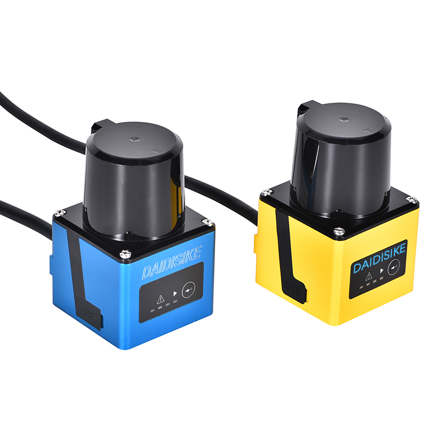
Since this is our site, a straight statement of where we play on R15.08 projects. DAIDISIKE manufactures the onboard and perimeter laser scanners that integrators specify into the safety functions described above. The DLD05A3 (5 m) and DLD20A5 (20 m) cover most onboard AMR/AGV obstacle-avoidance use cases; the DLD30T-5N at 40 m and SDLD-05A TOF unit address perimeter and fixed-station roles. On the fixed-station side, our DQSA area light curtains and DQA point-of-operation curtains handle the dock and pick-station guarding that has to dovetail with the vehicle safeguarding. DAIDISIKE has supplied safety sensors into automotive, electronics and logistics OEMs — including leading EV manufacturers, global 3C electronics OEMs, home-appliance makers, Tier-1 contract assemblers and display-module producers — over many years.
What we will not tell you is that buying a particular scanner model makes a deployment R15.08 compliant. Compliance is a system property, not a part number. Where we can usefully help is on the device-selection conversation — range, field sets, mounting, interface to the safety controller — inside the broader design your integrator owns.
The bottom line
R15.08 is not an exotic standard. It is the document that quietly defines “done properly” for industrial mobile robots in North America, and it has matured fast enough that buyers can no longer wave it off as draft work. The three-part split is the most useful thing about it — it forces manufacturers, integrators and users to be explicit about who owns which safety obligation, and it makes the hand-offs visible. If you are specifying an IMR fleet, ask the vendor about Part 1 conformance, ask the integrator about Part 2 deliverables, and put a Part 3 programme on your own EHS roadmap. Then the safety LiDAR scanner choices, the field-set design and the fixed-station guarding all sit inside a frame that actually holds together.