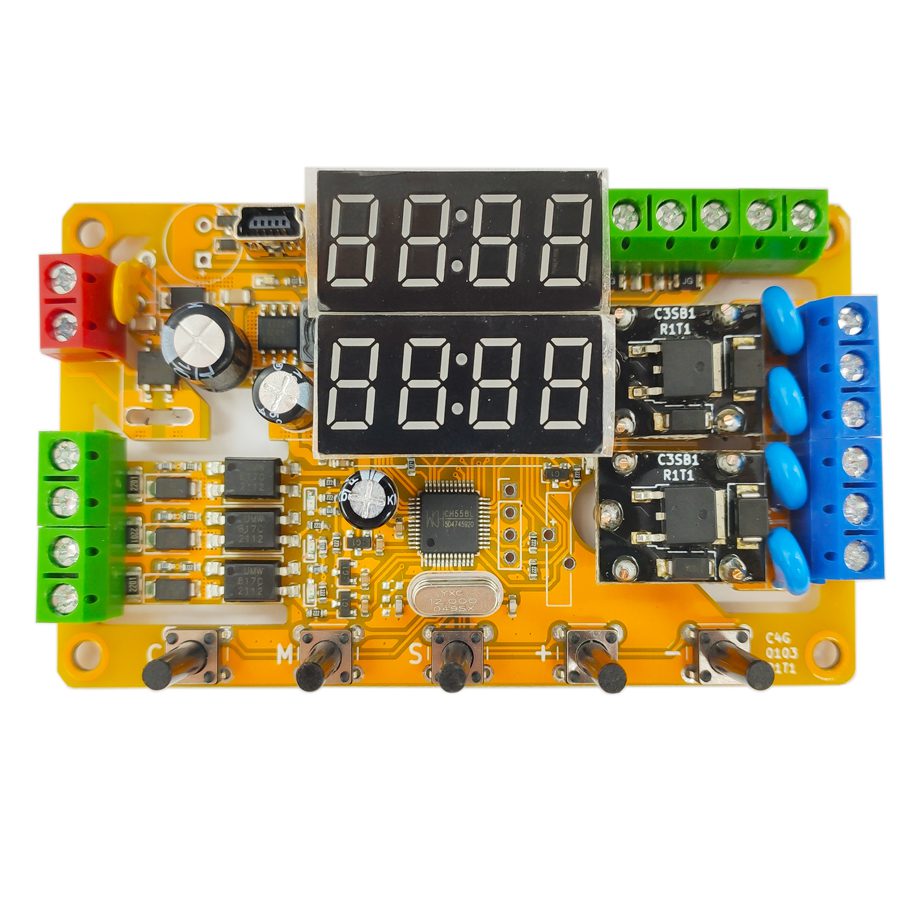
The program software adopts the shell technology. Some popular anti-virus software may have false alarm issues. Please add trust. This module is a multi-functional dual-channel digital delay module with a dedicated integrated circuit as the core. It has three digital signal inputs, two analog signal inputs and two relay outputs, and has a digital tube and buttons for on-site configuration functions. Depending on the model, its output can be a relay or a transistor. The two outputs can act independently or jointly to achieve various complex delay functions. Some models have a high-precision real-time clock that can trigger the module to act at a fixed time point. Some models have wireless functions and can be remotely triggered by a remote control. It can be controlled by the MODBUS communication protocol.
Product Features
High Flexibility
Three-channel high-voltage isolated optocoupler isolated digital trigger input
Two-channel arc suppression relay or transistor digital output
One-channel non-isolated differential external analog voltage detection
Analog voltage detection can operate in hysteresis mode or range mode
Up to 100 independent delay modes
High Usability
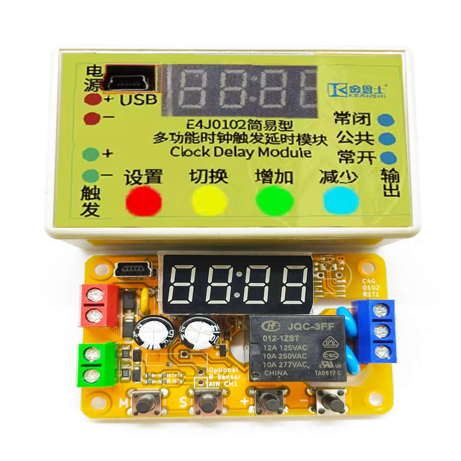
Built-in digital tube and keys for on-site function setting
Configurable via USB connection to a computer
High Expandability
Controllable via USB interface
Expandable with one RS-485 serial port and controllable via MODBUS-RTU protocol
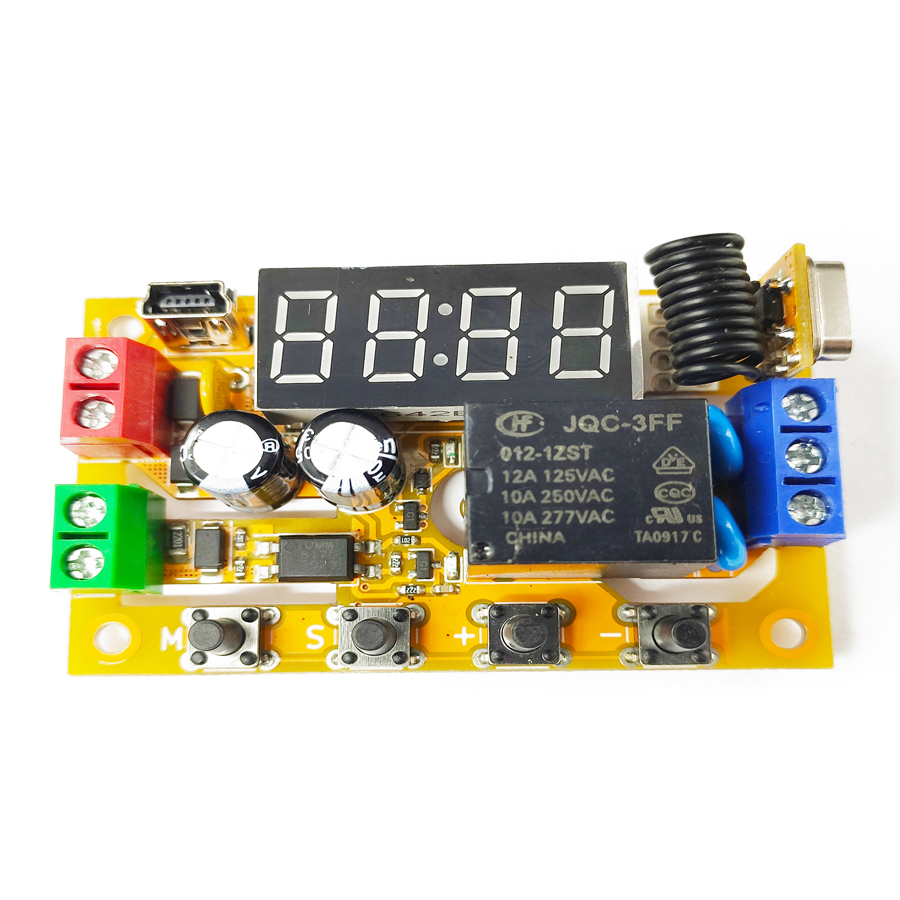
Expandable with remote control function and trigger module using remote controller
Expandable with real-time clock function and trigger module at a certain time point
Firmware upgradeable to obtain new expansion functions
High Reliability
True industrial-grade measured 2000V EFT and 4000V ESD tolerance
Reverse power protection, overcurrent protection and surge protection
Printed circuit board high-voltage side creepage distance slot strictly complies with safety regulations
Introduction
This product is a multifunctional dual-channel digital delay module with a dedicated integrated circuit at its core. It features three digital signal inputs, two analog signal inputs, and two relay outputs. It also has a digital tube and buttons for on-site configuration. Depending on the model, its output can be either a relay or a transistor. The two outputs can operate independently or in conjunction to achieve various complex delay functions. Some models are equipped with a highly accurate real-time clock that can trigger the module's operation at a fixed time point. Some models have wireless functionality and can be remotely triggered using a remote control. Some models also have a 485 communication function and can be controlled using the MODBUS communication protocol. All models have USB and serial port functions, allowing them to be connected to a computer for settings or firmware upgrades. By upgrading the module to the latest firmware, it can acquire new functions. At the factory, the default delay accuracy is one ten-thousandth within the full temperature range.
Introduction to MODBUS-ASCII Protocol
The content of each field in the MODBUS-ASCII protocol is exactly the same as that in the MODBUS-RTU protocol. The only difference is that ASCII requires the use of numeric characters to express instructions. Additionally, the ASCII protocol requires a colon (:) at the beginning and a carriage return and line feed (\r\n, 0x0D 0x0A) at the end. The checksum used in the ASCII protocol is also different from that in the RTU protocol, being LRC checksum. Compared to the RTU protocol, the ASCII protocol is easier to read, write and program, but it has a lower information density and poorer checksum reliability. Generally, it is only used in situations where compatibility with some old industrial control equipment is required. This product can intelligently distinguish between ASCII commands and RTU commands, and they will not interfere with each other. Since the support for the ASCII protocol is an additional feature, the maximum character interval still follows the agreement of the RTU protocol [1]. The maximum length of the ASCII format supported by this product is 480 bytes; ASCII commands exceeding this length will be directly truncated. For detailed information on the ASCII format and LRC checksum, please refer to relevant materials. Here, we only provide a comparison example of the ASCII format and the RTU format; it can be seen that the ASCII format is about twice as long as the RTU format.
Write Output
The "Write Output" is responsible for controlling the connection and disconnection of the module relay. If you want to connect the relay, you need to click on the button image to the left of "Write Output" to switch the image button to the connected state (yellow). Then click "Write Output", and the software will communicate. Wait for the communication to complete, and the relay will be connected. Conversely, if you want to disconnect the relay, just switch the image button to the disconnected state (gray), and then click "Write Output".
Read Trigger Status
The "Read" button in the trigger status area is responsible for reading the current state of the trigger terminal. If the voltage is higher than 3V, it is regarded as a high level and the status image turns yellow. If the voltage is lower than 3V, it is regarded as a low level and the status image turns gray. This function is affected by the input polarity setting; if the input polarity is set to reverse, the high level will return a low level and the low level will return a high level. When there is voltage at the optocoupler terminal, it is equivalent to a high level; when there is no voltage at the optocoupler terminal, it is equivalent to a low level. When the analog input is valid after being processed by the discrimination rule, it is equivalent to a high level; when the analog input is invalid after being processed by the discrimination rule, it is equivalent to a low level.
Real-time Clock Application Case
A farm is transforming into smart agriculture and requires automatic irrigation and fertilization at fixed times every day. The time points and working methods for irrigation and fertilization are different. The irrigation time is 5:00 a.m., and the irrigation lasts for 20 minutes. Considering the soil's permeability, the 20 minutes should be divided into 4 segments, each lasting 5 minutes, with a 15-minute interval in between to allow for soil absorption and prevent water loss. The fertilization time is 9:00 a.m., and the fertilization lasts for 10 seconds. Besides the automatic start of irrigation and fertilization at fixed times, the start and stop of irrigation and fertilization can also be controlled by buttons.
Requirement Analysis
The application uses the real-time clock function and two relay outputs. The power supply voltage of the product is 12V, and the E4J0103M212111 model with real-time clock function can be used to complete it. Channel 0 is used to control the irrigation device, and the configuration of channel 0 is as follows: F--0:0000, normal input and output; F--1:3004, rising edge trigger, connect and delay A, disconnect and delay C, repeat L times, stop and disconnect the output after the rising edge delay; P--A:4005, 5 minutes, the start time of irrigation; P--C:4015, 15 minutes, the interval time; P--L:0004, cycle 4 times, for 4 segments of irrigation time. Finally, set the trigger time point of channel 0 to 5:00 a.m. Channel 1 is used to control the fertilizer device, and the configuration of channel 1 is as follows: F--0:0000, normal input and output; F--1:1006, rising edge trigger to connect, delay A and disconnect, repeat the rising edge delay to stop and disconnect the output; P--A:2010, 10 seconds, the fertilization time. Finally, set the trigger time point of channel 1 to 10:00 a.m.
Frequently Asked Questions
Is the E4J0103 a safety relay or a programmable delay module?
The E4J0103 is a multi-functional dual-channel digital delay module, not a safety-rated relay. It uses a dedicated integrated circuit to provide programmable timing with three optocoupler-isolated digital inputs, two analog inputs and two relay or transistor outputs. For SIL/PL-rated functions you would still pair it with a dedicated safety relay; the E4J0103 handles flexible delay, sequencing and linkage logic on a DIN-friendly module.
How many delay modes does the E4J0103 support and how is it configured?
It supports up to 100 independent delay modes. You can configure it three ways: on the device itself using the built-in digital tube and buttons, over USB from a computer, or remotely through an RS-485 serial port. Each channel uses F-, P-, A-, C- and L- parameters to set trigger edge, on/off delays, intervals and repeat cycles, so the two outputs can act independently or jointly.
Does the E4J0103 support MODBUS-RTU and MODBUS-ASCII over RS-485?
Yes. The module can be expanded with an RS-485 serial port and controlled via the MODBUS protocol. It intelligently distinguishes MODBUS-RTU from MODBUS-ASCII commands, so the two will not interfere. MODBUS-ASCII frames begin with a colon, end with CR/LF and use LRC checksum; the maximum supported ASCII length is 480 bytes, with longer commands truncated. USB configuration and firmware upgrades are also supported.
What inputs, outputs and protection does the E4J0103 provide?
Each module has three high-voltage isolated optocoupler digital trigger inputs, one non-isolated differential analog voltage input that works in hysteresis or range mode, and two arc-suppression outputs that are relay or transistor depending on model. It is rated for measured 2000 V EFT and 4000 V ESD tolerance, with reverse-power, overcurrent and surge protection plus creepage-distance slots on the high-voltage side.
Can the E4J0103 trigger outputs at a fixed time of day or wirelessly?
Some models include a high-precision real-time clock, so an output can be triggered automatically at a set time point — for example irrigation at 5:00 a.m. and fertilization at 9:00 a.m. on a smart farm. Other models add a wireless function for remote-control triggering. Default delay accuracy is one ten-thousandth across the full temperature range, and new features can be added by firmware upgrade.