Specification Table of DA31 Series Safety Relay
| Item | Specification Description |
|---|
| Power Supply Voltage | 24V DC, Voltage Tolerance +10%/-20% |
| Power Dissipation | 2.9W |
| Relay Safety Output | 3 Normally Open Instantaneous Safety Contacts (3NO) + 1 Normally Closed Instantaneous Safety Contact (1NC) |
| Transistor Signal Output | <500mA, 24V DC |
| Relay Contact Capacity | AC-1: 6A/250VAC/1500VA; AC-15: 4A/240VAC; DC-1: 6A/24VDC/150W; DC-13: 4A/24VDC |
| Maximum Switching Capacity | 12A (distributed across all safety output contacts) |
| Contact Resistance | <100mΩ |
| Minimum Load | 10mA/5V |
| Contact Material | AgSnO2 + 0.2μmAu |
| Output Fuse (External Connection) | 5A gL/gG |
| Release Response Time | <30ms (from input to output) |
| Input Component Tail Detection Resistance | 1kΩ~10kΩ |
| Electrical Life | 80,000 cycles |
| Pollution Degree | 2 |
| Operating Temperature | -25°C to 85°C |
| Working Humidity | 35%-85% (no icing or condensation) |
| Impulse Withstand Voltage | 2.5kV |
| Protection Grade | Housing IP30, Terminal IP20, Recommended for Installation in Cabinet or Housing IP54 |
| Storage Temperature | -40°C to 105°C |
| Shell Material | Flame Retardant PA66 |
| Installation Method | Standard 35mm DIN Rail/Spring Clip |
| Dimensions | 112mm × 99.5mm × 22.6mm |
| Weight | 172g |
| Connection Parameters (Rigid Wire Cross-Sectional Range) | 0.5~2.5mm² |
| Connection Parameters (Flexible Wire Cross-Sectional Range) | 0.5~2.5mm² |
| Minimum Conductor Cross-Section | AWG 24 |
| Maximum Conductor Cross-Section | AWG 12 |
| Strip Length | 8mm |
| Minimum Tightening Torque | 0.5 Nm |
| Maximum Tightening Torque | 0.6 Nm |
Technical Parameters of DA31 Series Safety Relay
The technical parameters of the DA31 series focus on safety performance and electrical characteristics. The power supply is 24V DC, with a tolerance range of +10% to -20%, and power consumption not exceeding 2.9W. The input supports dual-channel safety inputs, capable of detecting tail resistance of 1kΩ~10kΩ for open-circuit detection and channel mutual inspection. The output provides 3 normally open (NO) and 1 normally closed (NC) instantaneous safety contacts, with contact capacity supporting AC/DC loads, and a maximum switching current of 12A. The response time is less than 30ms, ensuring quick release. Electrical life reaches 80,000 cycles, suitable for pollution degree 2 environments. Wide operating temperature range from -25°C to 85°C, humidity 35%-85% without condensation. Protection grade is IP30 (housing) and IP20 (terminals), with impulse withstand voltage of 2.5kV. Connections use screw or spring terminals, supporting AWG 24-12 wires. The overall design complies with EN/ISO 13849-1 Cat.4/PLe and IEC 62061 SiL3 standards, ensuring reliable monitoring in high-risk industrial sites.
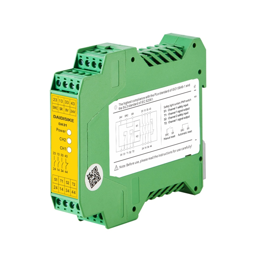
Working Principle of DA31 Series Safety Relay
The core working principle of the DA31 series safety relay is based on a dual-channel redundant safety monitoring circuit design (Dual-Channel Redundant Safety Monitoring), which is a fail-safe architecture that ensures system safety even in the event of a single-channel failure. The relay uses high-speed mutual verification technology (High-Speed Mutual Verification) to monitor input signals from two independent channels in real time. If the signals from the two channels are inconsistent or an abnormality is detected (such as open circuit, short circuit, or external interference), the system immediately cuts off the output to prevent hazardous actions.
The specific workflow is as follows:
- Input Detection: The input terminals (S1/PNP signal 1 and T2/S1) receive signals from safety devices (such as safety light curtains or emergency stop buttons). It supports PNP or NPN signal sources and has built-in tail resistance for open-circuit detection. Channel 1 and Channel 2 perform mutual inspection; if the signals are synchronous and valid, the internal relay is activated.
- Logic Processing: The built-in microcontroller verifies signal integrity and supports configuration via DIP switches for automatic reset (Automatic Reset) or manual reset (Manual Reset). In manual mode, an external reset button is required to confirm safety recovery.
- Output Control: Once the input is valid, the output 3NO+1NC contacts supply power to actuators (such as motor contactors). The release response time is <30ms, ensuring quick disconnection in emergency situations. PLC signal output is used for system feedback.
- Fault Handling: It adopts force-guided contacts (Force-Guided Contacts); if one contact sticks, the other will detect and report the fault. Compliant with functional safety standards, it achieves PL e/Cat.4 level safety through redundancy and self-diagnosis.
- Application Extension: In safety light curtain applications, when an intrusion is detected by the light curtain, the input is interrupted, and the relay output immediately stops machine operation. It supports various wiring diagrams, such as dual-channel emergency stops and safety door locks, ensuring multifunctional adaptability in industrial automation.
This principle draws from safety integrated systems (Safety Integrated System, SIS) in industrial automation, emphasizing preventive maintenance and minimization of risk propagation to ensure protection of personnel and equipment.